background image

6

EN

digital true RMS multimeter BE52

The design of a measurement device determines in which
environments and for which voltages it can be safely used. What
is important in this connection for example is the touchability of
live parts, anti-kink protection guards on the measuring lines or
the insulation. Depending on the design details, the
measurement device can carry out safe measurements up to a
specific voltage in one or several overvoltage categories. The
measurement category is specified on the measurement device
as well as in the operating manual.
The measurement category is indicated including the maximum
voltage height, which can either be 300, 600 or 1000 Volt. The
designation CAT III/1000 V for example means that the
measurement device may be used in low-voltage indoor
installation for voltages up to 1000 volts.
Often several values are indicated on the device, for instance
CAT III/ 1000 V and CAT IV/600 V. In these cases, different
maximum voltages apply to the stated scopes of application. If
no measurement category is specified, the measurement device
is only considered as safe in measurement category CAT I.
This measurement device is suited for category CAT III (600 V).

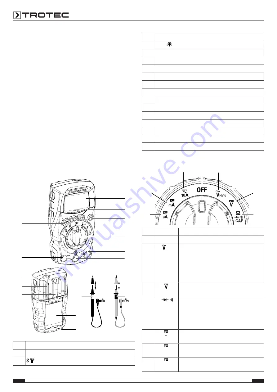
Device depiction

1

3

4

6

7

2

8

12

14

9

16

10

15

5

11

13

No.

Designation

1

LC display

2

 button

No.

Designation

3

HOLD

/

 button

4

Rotary switch

5

Measuring socket 

6

Measuring socket 

COM

7

Red measuring tip

8

Black measuring tip

9

Fold-out stand

10

Fuse compartment

11

Battery compartment

12

Holding fixture for measuring tips

13

Work light

14

Measuring socket 

10 A

15

MODE

 button

16

MAX/MIN/R

 button

Rotary switch

22

23

17

18

19

20

21

No.

position

Description

17

OFF

Device is switched off.

18

Hz%

AC voltage:
0.001 mV to 1000 V
Frequency measurement:
0.01 Hz to 9999 Hz
Duty cycle:
1 % to 99 %

19

DC voltage:
0.1 mV to 1000 V

20

Ω/

/

CAP

Resistance measurement:
0.1 Ω to 40 MΩ
Diode test / continuity measurement
Capacitance measurement:
0.01 nF to 4000 μF

21

µA

Direct and alternating current:
up to 6000 µA

22

mA

Direct and alternating current:
up to 400 mA

23

10A

Direct and alternating current:
up to 10 A

Summary of Contents for BE52

Page 1: ...TRT BA BE52 TC220328TTRT03 001 EN BE52 EN OPERATING MANUAL DIGITAL TRUE RMS MULTIMETER ...

Page 2: ...structions must be observed You can download the current version of the instructions and the EU declaration of conformity via the following link BE52 https hub trotec com id 46448 Safety Read this manual carefully before starting or using the device Always store the manual in the immediate vicinity of the device or its site of use Warning Read all safety warnings and all instructions Failure to fo...

Page 3: ...of an electric shock at these voltage levels Ensure that the measuring area has zero potential and the capacitors are discharged before you carry out diode resistance or continuity tests Disconnect the measuring lines from the measuring area before switching over the device to diode resistance or continuity tests if you have previously carried out measurements on live components Intended use Only ...

Page 4: ...mmerse the device and the accessories in water Make sure that no water or other liquids can enter the housing Warning of electrical voltage Work on the electrical components must only be carried out by an authorised specialist company Warning Risk of suffocation Do not leave the packaging lying around Children may use it as a dangerous toy Warning The device is not a toy and does not belong in the...

Page 5: ...on a PC you can even use report templates and ready made text blocks for various fields of application to turn the data into professional reports Overvoltage protection and measurement category The power grid is permanently subjected to short time voltage peaks the so called voltage surge which can be very low for instance when a light switch is actuated but also very high when a network operator ...

Page 6: ...different maximum voltages apply to the stated scopes of application If no measurement category is specified the measurement device is only considered as safe in measurement category CAT I This measurement device is suited for category CAT III 600 V Device depiction 1 3 4 6 7 2 8 12 14 9 16 10 15 5 11 13 No Designation 1 LC display 2 button No Designation 3 HOLD button 4 Rotary switch 5 Measuring ...

Page 7: ...ve humidity for storage 80 Operating height above sea level Max 2000 m 7000 ft Type of protection IP40 Weight approx 140 g Dimensions length x width x height 121 x 67 x 45 mm Automatic switch off after approx 15 minutes of non use Safety This measuring device is designed for indoor use and complies with overvoltage category CAT III 600 V Measuring ranges Function Measuring range Resolution Accurac...

Page 8: ...g used observe the following storage conditions dry and protected from frost and heat protected from dust and direct sunlight the storage temperature complies with the values specified in the Technical data Remove the batteries from the device Operation Warning of electrical voltage Electric shock due to contact with live parts When using the measuring tips make sure not to reach behind the protec...

Page 9: ...tion exceedance of the measuring range will be displayed IMPORTANT INFORMATION ON THE MEASURING PROCESS Warning of electrical voltage Improper handling of the measuring device entails a risk of electric shock Before carrying out voltage measurements observe the following Never apply a voltage exceeding the rated nominal voltage of the measuring device between the connections or between the connect...

Page 10: ...ng time Then press briefly to adapt the decimal places Measuring DC voltage 1 Turn the rotary switch to position 19 2 Insert the plug of the black measuring tip into the COM 6 measuring socket and the plug of the red measuring tip into the VΩ 5 measuring socket 3 Connect both measuring tips to the measuring object with correct polarity black to minus red to plus ð If the input voltage is negative ...

Page 11: ...ceedance of the measuring range appears after the manual range selection immediately switch over to the respectively next higher range If the OL indication appears and the maximum range has been set already or in case of the automatic range selection immediately switch off the voltage supply at the measuring object and disconnect the measuring device from the measuring object Info If you have sele...

Page 12: ...voltage in the capacitor can lead to a destroyed measuring device Never connect the measuring inputs to a voltage source This will destroy the measurement device For reasons of safety measure whether there is a residual charge in the capacitor using the VDC range before you perform a capacitance measurement 1 Set the rotary switch to the Ω CAP position 20 then use the MODE button 15 to select the ...

Page 13: ...ess the button 2 briefly to switch on the work light Press the button briefly again to switch off the work light again Enabling or disabling Bluetooth The device is provided with a Bluetooth function that allows you to connect the device with a terminal device mobile phone tablet etc on which the MultiMeasure Mobile App is installed see chapter MultiMeasure Mobile App Press the button 2 for a long...

Page 14: ...ing the rotary switch at the multimeter to the desired measuring mode For some measuring modes you additionally have to press the MODE button see Operation chapter As an example the screen for the AC voltage measuring mode is shown here Sensors Measurements Reports Customers Settings AC voltage HOLD REL MIN MAX PEAK The last 12 values measured over time and the corresponding unit are displayed in ...

Page 15: ...ording is in progress You can press this flashing symbol or the free area below the measurement value display to open the context menu to stop recording You can choose from saving or discarding the record after stopping recording Menu bar The functions of the MultiMeasure Mobile App are controlled via the menu bar from which the submenus can be accessed Info Depending on the operating system of th...

Page 16: ...ues and saves it as a PNG file Generate image overlay Combines a background image with the representation of the measured values Colour scaling Allows you to adjust the colour display of the measured values Submenu reports The reports generated in the MultiMeasure Mobile app are short reports providing a fast and simple documentation You can select from the following options in the REPORTS submenu...

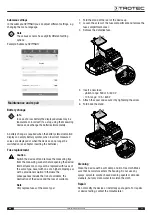
Page 17: ... the measuring tips from the measuring sockets before opening the device Internal fuses may only ever be replaced with fuses of the same type never with one of a higher amperage or with a provisional solution Otherwise the consequences include the risk of accidents the destruction of the device and the loss of warranty Note Only replace fuses of the same type 1 Fold the stand at the rear of the de...

Page 18: ...ects for the environment and human health caused by the disposal of hazardous substances potentially contained in the equipment In the European Union batteries and accumulators must not be treated as domestic waste but must be disposed of professionally in accordance with Directive 2006 66 EC of the European Parliament and of the Council of 6 September 2006 on batteries and accumulators Please dis...

Page 19: ...Trotec GmbH Grebbener Str 7 D 52525 Heinsberg 49 2452 962 400 49 2452 962 200 info trotec com www trotec com ...

Reviews: