Service Sheet No. 1004 (contd.)
Dismantling Drive Side of Unit
With the spanner provided in the toolkit remove the two sparking plugs, take off the two ~ in. nuts holding
the rocker box cover, remove the steel washers and fibre washers and remove the cover. Examine the cover
gasket to decide whether or not it can still be used. If the gasket is damaged in any way, as for example, if
parts of it have adhered to the cylinder head, or if it is compressed too thin, it is advisable to use a new one.
Slacken off the two union screws holding the oil feed pipe to the rocker box and crankcase, and remove the
pipe, leaving the unions screwed into both the crankcase and cylinder head.
Remove the seven nuts and washers which hold the cylinder head to the block. Four of these are at the rear
inside the rocker box and three at the front adjacent to the sparking plugs. The smaller ring spanner provided in
the toolkit is the most suitable tool to use on these nuts. Take off the cylinder head and in this case, although the
gasket may appear to be in good condition, since it, is, a, comparatively cheap and certainly an important item, it
is advisable to use a new one when reassembling.
There may be no need to dismantle the rocker assembly but in case this operation is described at a later
stage.
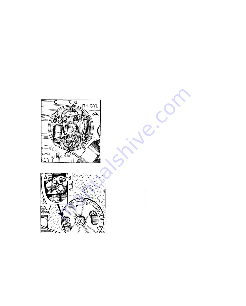
A standard type of screwdriver can be used to take off the contact breaker cover by removing the two 3/16 in.
screws, following which the cover can be placed to one side after the rubber grommet holding the leads has been slid
out of the "U" shaped slot in the cover. Unscrew the two long hexagon nuts (C) Fig. 4, which are slightly to the
left and right of the contact breaker plate and take off the plate complete with the leads after disconnecting the
black and white lead from the left-hand
ignition coil and the
black and yellow lead from the right-hand coil.
The contact breaker cam and automatic advance and retard unit is retained by the centre bolt which is now
175
Contact breaker
letters shown are not
for this page
Summary of Contents for TW2
Page 1: ......
Page 55: ...SERVICE SHEET No 1050 contd Wiring Diagram 6 Volt Model...
Page 57: ......
Page 58: ...i SERVICE SHEET No 1050 contd...
Page 61: ......
Page 66: ......
Page 73: ......
Page 74: ......
Page 75: ......


