A
Q U A S E N S A T I O N
A S 2 0 0 0 T / A S 2 0 0 0
15
FITTING THE RISER RAIL
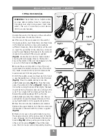
Decide the position for the rail on the wall within
the shower area. Proceed as follows:
A
Offer one of the two brackets to the wall for
the lower position only. Note there are three holes
in the brackets but two screws will usually be
sufficient. However, the centre hole must be used
so mark this and either of the other two. Drill and
plug the wall. Replace the bracket to the wall and
secure to the wall with the screws supplied
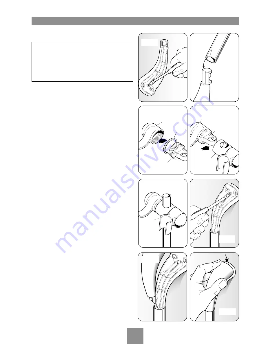
(fig.28)
. Locate the rail onto this lower bracket
ensuring the rail engages fully on the bracket.
Ensure the indent in the riser rail engages into the
cut-out on the bracket end
(fig.29)
.
B
Locate the second bracket on top of the rail.
Again mark the centre hole plus one of the other
two holes. Ensure the rail is vertical. Remove the
bracket and rail. Drill and plug the wall.
C
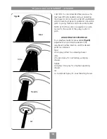
With the saddle, spacer and lever parts to hand,
screw the saddle two or three turns into the lever
(fig.30)
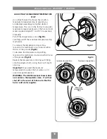
. Place the saddle and lever into the
slider/holder assembly
(fig.31)
so that the holes
align, then slide onto the rail
(fig.32)
. Tighten to
the rail by turning the lever. When tight, the lever
should be facing forwards and not pointing to the
wall. If not, slacken off and remove from the rail.
Rotate the saddle and lever 180° within the
slider/holder assembly then replace onto the rail
and tighten. Ensure the tapered thin end of the
spray head holder is in the uppermost position.
D
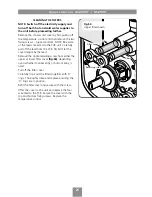
Place the rail onto the installed lower bracket.
Replace the upper bracket onto the rail and secure
the bracket to the wall with the screws supplied
(fig.33)
.
E
Place a trim cover onto each bracket ensuring
the large protrusion at the narrow end of the trim
cover, engages into the slot between the rail and
bracket
(fig.34)
before pushing and clicking the
other end into place
(fig.35)
. Should the need
arise, the trim covers can be removed by inserting
WARNING:
Check there are no hidden cables
or pipes before drilling holes for wall plugs.
Use great care when using power tools near
water. The use of a residual current device
(RCD) is recommended.
Saddle
Lever
Slider/holder
assembly
Saddle
Lever
Spacer
Tapered
thin end
Fig.30
Fig.31
Fig.32
Fig.34
Fig.33
Fig.28
Fig.29
Fig.35
Summary of Contents for Aquasensation AS2000
Page 28: ...UKAS QUALITY MANAGEMENT 003 ...


