


• Connect DC Wiring:
Though your Inverter is a high-efficiency converter of electricity, its rated output
capacity is limited by the length and gauge of the cabling running from the battery to the unit. Use the shortest
length and largest diameter cabling (maximum 2/0 gauge) to fit your Inverter’s DC Input terminals. Shorter and
heavier gauge cabling reduces DC voltage drop and allows for maximum transfer of current. Your Inverter is
capable of delivering peak wattage at up to 200% of its rated continuous wattage output for brief periods of time.
Heavier gauge cabling should be used when continuously operating heavy draw equipment under these conditions.
Tighten your Inverter and battery terminals to approximately 3.5 Newton-meters of torque to create an efficient
connection and to prevent excessive heating at this connection. Insufficient tightening of the terminals could void
your warranty.
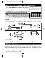
Connect your Inverter to your batteries using the following procedures:
DC Connectors
Battery Connection and Cable Sizing Chart
6
Mounting
WARNING! Mount your Inverter BEFORE DC battery and AC power connection. Failure to follow these
instructions may lead to personal injury and/or damage to the Inverter and connected systems.
Tripp Lite manufactures a variety of different Inverters with a variety of different mounting options for use in vehicular or non-vehicular
applications. Tripp Lite recommends permanent mounting of your Inverter. User must supply mounting hardware and is responsible for
determining if the hardware and mounting surface are suitable to support the weight of the Inverter. Contact Tripp Lite if you require further
assistance in mounting your Inverter.
A
B
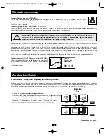
540 watts ÷ 12V =
45 DC Amps
45 DC Amps × 5 Hrs. Runtime
× 1.2 Inefficiency Rating =
270 Amp-Hours
• STEP 2: Determine DC Battery Amps Required
Divide the total wattage required (from step 1, above) by the battery voltage (12)
to determine the DC amps required.
• STEP3: Estimate Battery Amp-Hours Required (for operation unsupported by
the alternator)
Multiply the DC amps required (from step 2, above) by the number of hours you
estimate you will operate your equipment exclusively from battery power
before you have to recharge your batteries. Compensate for inefficiency by
multiplying this number by 1.2. This will give you a rough estimate of how
many amp-hours of battery power (from one or several batteries) you should
connect to your Inverter.
NOTE! Battery amp-hour ratings are usually given for a 20-hour discharge rate. Actual amp-hour capacities are less
when batteries are discharged at faster rates. For example, batteries discharged in 55 minutes provide only 50% of
their listed amp-hour ratings, while batteries discharged in 9 minutes provide as little as 30% of their amp-hour ratings.
Application Guide
(continued)
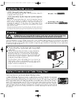
5.57 in.
(14.16 cm.)
15.02 in.
(38.12 cm.)
5.57 in.
(14.16 cm.)
A
M
B
Using the measurements from the diagram, install two user-supplied
¼" (6 mm) fasteners into a rigid horizontal surface, leaving the heads
slightly raised.
Slide the Inverter forward over the fasteners to engage the mounting
feet molded on the front of the Inverter cabinet. Install and tighten
additional user-supplied ¼" (6 mm) fasteners into the mounting feet
molded on the rear of the Inverter cabinet. The rear feet extend beyond
the unit’s cabinet to provide for adequate ventilation space behind the
cooling fan(s); they should not be removed.
The polycarbonate cabinet and mounting feet of your Inverter are
durable enough to allow for vertical mounting as well, if your vehicle
compartment requires this configuration. For vertical mounting, the con-
trol panel of the Inverter should face up.
Allow 2" (5 cm.) minimum front and rear clearance for adequate ventilation.
200702194 PowerVerter DC-AC Owner’s Manual CH.qxd 2/23/2007 4:02 PM Page 6


