


3
Feature Identification
(continued)
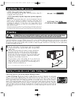
Identify the premium features on your specific model and quickly locate instructions on how to maximize their use.
ON-OFF-REMOTE Switch:
• Move the switch to the ON position to have your Inverter
provide connected equipment with AC power by converting
DC power from an attached battery.
• Leave the switch in the OFF position when not using
connected equipment to prevent battery drain.
• Set the 3-position switch to REMOTE to control your Inverter
at a distance with a wired remote control module (Tripp Lite
Model # APSRM4; sold separately).
“LOAD” LEDs:
intuitive “traffic light” signals show the
approximate connected equipment load level. See Operation
section for instructions on reading the indicator lights.
“BATTERY” LEDs:
these three lights will turn ON in several
sequences to show approximate battery charge level. See
Operation section for instructions on reading the indicator lights.
DC Power Terminals:
connect to your battery terminals. See
Battery Connection section for instructions.
Resettable Circuit Breaker:
protects your Inverter against
damage due to output overload. If the breaker trips, remove
some of the load on the Inverter to prevent overload, then wait
at least 1 minute to allow components to cool before resetting
the circuit breaker.
NEMA 5-15/20R AC Receptacles:
allow you to connect
equipment that would normally be plugged into a utility outlet.
Remote Control Module Connector:
allows remote monitoring
and control with an optional module (Tripp Lite Model
#APSRM4; sold separately). See remote module owner’s
manual for connection instructions.
Battery Charge Conserver (Load Sense) Dial:
conserves
battery power by setting the low-load level at which the Inverter
automatically shuts off. See Configuration section for setting
instructions.
Main Ground Lug:
properly grounds the Inverter to
vehicle grounding system or to earth ground. See Configuration
section for instructions.
Multi-Speed Cooling Fan:
quiet, efficient fan prolongs equipment
service life.
Ignition Switch Control Jack (side panel, not shown):
use to
connect the Inverter to your vehicle's ignition switch (with user
supplied cable) in order to automatically control the Inverter
with the vehicle's ignition switch. See Operation section.
Inverter ON/OFF Indicator Jack (side panel, not shown):
use to connect the Inverter to a user-supplied on/off indicator.
See Operation section.
1
2
3
4
5
7
8
9
LOAD
SENSE
LOAD
REMOTE
LOW
MED
HIGH
ON OFF REMOTE
BATTERY
HIGH
MED
LOW
MAX OFF
20A
LOAD C/B 25 A
1
3
2
4
5
Front View
9
Rear View
Side Mounted,
Not Shown
10
11
10
7
8
11
6
12
6
Side Mounted,
Not Shown
12
Operation
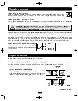
Switch Modes
Switch between the following operating modes as appropriate to your situation:
ON:
Move the switch to the ON position to have your Inverter provide connected equipment with AC power by
converting DC power from an attached battery.
OFF:
Move the switch to the OFF position to shut down the Inverter completely, preventing it from drawing power from
the battery. Leave the switch in the OFF position when not using connected equipment to prevent battery drain. Also use
this setting to automatically reset the unit if it shuts down due to overload or overheating. First remove the excessive load
or allow the unit to sufficiently cool (applicable to your situation). Switch to OFF, then back to ON. If unit fails to reset,
remove additional load or allow the unit to cool further and try again.
REMOTE:
Move the switch to the REMOTE position to control your Inverter at a distance with a wired remote
control module (Tripp Lite Model # APSRM4; sold separately). Consult the remote control module owner's manual for
more information.
REMOTE
REMOTE
REMOTE
Continued on next page.
200702194 PowerVerter DC-AC Owner’s Manual CH.qxd 2/23/2007 4:02 PM Page 3


