


Trio Pro Pilot Manual 4.1
38
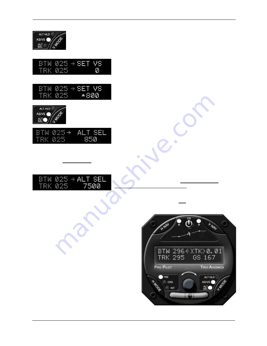
Press the
V MODE
button to advance to the
V MODE
display. The first display
screen will show an
ALT HLD
message.
Press the
V MODE
button again to advance to the
SET VS
(set vertical speed) screen. When first entering this screen,
the rate will always be “0” unless previously adjusted.
Rotate the encoder knob to set in the desired climb rate – in
this case let’s use 800 fpm. Note that the
AS/VS
LED
illuminates when a rate has been dialed into the display.
To enter the target altitude, press the
V MODE
button again to advance to the
ALT
SEL
screen.
Note that the system has “snapshot” our current altitude and
displays it on the screen. Since we are still on the ground, it
will show the same field elevation that we had previously
adjusted when we first turned the system on.
Rotate the encoder to enter the desired altitude. Each “click” of the encoder will change the altitude by
100 feet. If we press and hold the encoder knob while turning, it will change the altitude by 1,000 feet
per “click”.
Select the target altitude of 7,500 feet as shown, and press the
encoder knob to enter this value. If the encoder is not
pressed, the value will not be entered.
Notice that the
ALT SEL
LED also illuminates as we enter the altitude. Since both LEDs are illuminated
it informs us that a climb will be initiated when the
V NAV
servo is engaged and the encoder knob has
been pressed while either the
VS SET
or
ALT SEL
screen is displayed
Pressing the
H MODE
button at this point will devote
the screen and encoder to the horizontal navigation
functions. However, the
V MODE
LEDs will continue
to show that values have been entered in the
VS SET
and
ALT SEL
registers (they are now “armed” and
ready
to execute).
The Pro Pilot is now properly set for the flight. The
GPS has a flight plan and the climb rate and target
altitude have been entered.
After takeoff, and safely out of the airport traffic
pattern, we engage the
H NAV
servo by pressing the
H NAV
button. The Pro Pilot is now controlling the
aircraft ailerons and guiding the airplane toward the
destination airport.
Assume that we are still close to our departure airport
and the class B airspace is still above us. At this point we can engage the vertical profile by pressing the