


TMCM-170 and TMCM-171 MODULE – Reference and Programming Manual
5
Copyright © 2005, TRINAMIC Motion Control GmbH & Co. KG
There is one PID parameter set for position maintenance and one parameter set for velocity mode.
For the first tests, you can set both parameter sets equal. After having found suitable values, the
velocity mode parameters should be set to “less stiff”, i.e. to lower values, to minimize regulation
oscillation during constant rotation. The switch-over between both sets is soft, and occurs between
stand still and the velocity given by “min speed for velocity PID”.
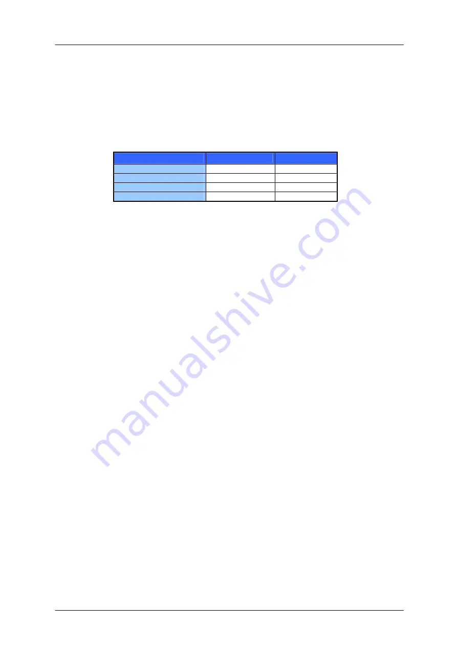
As you can see in the default value table, the positioning and velocity mode PID parameters in this
example have a relationship of about 4 to 1. But the I-Clipping parameter typically has the inverse
relationship: 1 to 4 in this example! This allows the I parameter to apply the same maximum torque
difference in both parameter sets.
Position
Velocity
P-Parameter
100 25
I-Parameter
167 42
D-Parameter
30 8
I-Clipping-Parameter
160 640
Table 1: Default PID Values
Attention: For all tests set the motor current limitation to a realistic value, so that your power supply
does not become overloaded during acceleration phases. If your power supply goes to
current limiting, the unit may reset or undetermined regulation results may occur.


