


IDX Manual (V1.15 / September 26
th
, 2008)
15
Copyright © 2005-2008, TRINAMIC Motion Control GmbH & Co. KG
5.3.1
EMV considerations
Due to the small form factor of the unit, it is not completely protected against electromagnetic
emissions resulting from switching operation. If your system is subject to CE testing and shows EMV
problems, i.e. due to some parts of the housing/cabling not being shielded, provide ferrite filters for
the positive power supply line and for the motor outputs near to the unit. A 470pF to 1nF (100V)
capacitor to GND then should be added externally to each ferrite filter.
5.4
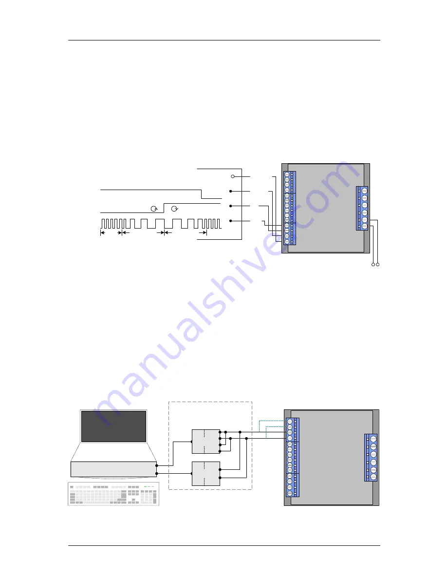
Connections for Step / Direction- Mode
The step-direction-mode is enabled if the acceleration is set to 0 (default) using the RS485 interface.
The example input signals of Figure 5.3 are schematically (see chapter 4.2 for more information):
Dir
Common
Disable
Step
PWR 12...50 V
TMCM-IDX
5 ... 24 V
Dir
Common
0 V
rotating direction
Disable
Common
0 V
rotation on off
at Vcommon or left open
Step
Common
0 V
Velocity Deceleration Acceleration
const.
Figure 5.3: Contacts for Step-Direction
The maximum step frequency is 350 kHz (limited by the opto couplers).
5.5
Connections for RS485 Interface
The RS485-mode allows for configuration of motor parameters as well as remote control of the
motor.
5.5.1
Interface installation
To connect the module to a PC a RS485 interface is required, for example TRINAMIC’s new USB-2-485
or any other RS485 adapter, like the standard RS232 to RS485-converters. Input A has to be connected
to RS485A of the IDX and Input B with RS485B.
TMCM-IDX
RS-232-port
USB-port
Terminal
alternative
RS
23
2
to
RS
48
5
4 3
2 1
US
B
to
RS
48
5
+
-
Either use a RS232 to
RS485 or alternatively
a USB to RS485 adapter
+
-
+
-
Figure 5.4: Contacts for RS485 with an adapter


