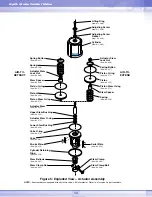
6
Note:
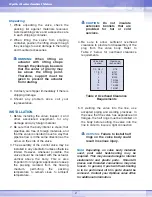
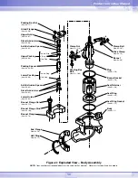
For ANSI Class 900 and above valves,
valve sizes up through 1.5-inch, the seat
retainer window should be placed in the body
with the window facing toward the valve
ports. For valves 2-inches or greater in size,
the bar of the retainer should face toward the
valve ports.
6. For air-to-open valves, place air under the
actuator piston to retract the plug.
7. Let down the plug and body squarely into
the body. Take caution as not to scratch the
plug as it enters the body.
8. To properly align the seat ring and plug, first
bring the bonnet bolting to finger tightness.
a. If the actuator is pneumatic, apply air
pressure above the piston to seat the
plug in the seat ring, then skip to step 9.
b. If the actuator is electric or hydraulic,
move the actuator stem down until it is
fully extended. Then retract the actuator
stem 1/8-inch/3.175-mm. Mount the
stem clamp onto the plug stem/actuator
limit switches according to the operating
manual of the actuator.
Note:
The following step (9) pertains only to
valves with pneumatic actuators. In the case
that an electric or hydraulic actuator is used,
return the plug to the mid stroke position and
proceed to tighten.
CAUTION:
For electric or
hydraulic actuators, failure to
return the plug to a mid stroke
position will cause damage to
the actuator and/or the valve
while the bonnet is being
tightened.
9. If the valve is air-to-close, skip this step and
continue to step 10. Check for proper plug
seating in air-to-open valves as follows: If
proper seating occurs, the bonnet flange
will be forced up against the finger tight
body with such force that it will not be
possible to wriggle the flange. If improper
seating occurred, the bonnet flange can be
wriggled with light hand force. If this
occurs, place air under the actuator piston
and retract the actuator to approximate
mid-stroke position. Turn the plug out of
the actuator stem one additional thread and
repeat the seating procedure described
above. When the bonnet flange becomes
tight against the finger tight body bolting,
the plug is then properly seated.
10. For pneumatic actuators, put the plug in
the closed position. For electric, hydraulic,
or mechanical actuators, move the plug to
the mid-stroke position. Tighten the bonnet
flange bolting in such a way that will
maintain the bonnet flange square (or
parallel) with the body. Tighten the first bolt
1/6 of a turn, then,tighten the bolt directly
opposite 1/6 of a turn and so on around the
flange. Tighten all the bolts firmly and
evenly to compress the bonnet gasket and
seat the bonnet. Torque the bonnet bolts to
the suggested torque values in Table 4.
Table 4: Suggested Bonnet Bolting Torque
Values (ft. lbs. /Nm, ± 10%)
11. To seat the plug, apply air over the piston.
For throttling valves, adjust the stem clamp
so that, with full instrument signal to the
positioner, the full signal scribe line on the
positioner cam points to the center of the
cam roller bearing.
Op
G
L
G
lobe Control Valve
Bolt Size
(inches)
5/8
3/4
7/8
1
1 1/8
1 1/4
1 3/8
1 1/2
1 5/8
1 3/4
1 7/8
2
Carbon Steel
80/108
140/190
230/312
350/475
510/690
730/990
990/1342
1320/1790
1710/2318
2170/2942
2700/3660
3350/4542
Stainless Steel
50/68
90/122
150/203
220/298
330/447
460/624
630/854
840/1140
1080/1484
1400/1898
1700/2305
2100/2847
Bolt/Stud Material


