8
Note:
The actuator stem bushings are
pressed into the yoke; it is not necessary to
remove the bushing in order to replace the
O-ring.
Actuator Reassembly
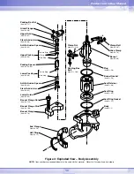
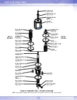
For actuator reassembly, refer to Figure 5.
Continue as follows:
1. All O-rings should be replaced and the new
ones should be lubricated. Most O-rings
can be lubricated with a silicone lubricant.
(Do not use a silicone lubricant on silicone
O-rings)
2. Be certain to clean and lubricate all internal
parts before beginning reassembly.
3. In the case that the actuator stem has been
removed, replace the piston stem O-ring,
and reassemble the piston and actuator
spacer on the actuator stem according to
the valve’s air-action. If air-to-close, the
spring button has to be inserted under the
actuator stem-retaining nut. Tighten the
retaining nut firmly.
4. For air-to-close configurations, place the
spring under the piston and insert the
actuator stem through the yoke – be careful
not to gall the stem or bushings. Be sure
that the spring is retained in the groove on
top of the yoke. For air-to-open
configurations, insert the actuator stem
through the yoke and place the spring and
spring button above the piston.
5. Mount the cylinder and make certain that
the yoke is pushed deep enough into the
cylinder for the retaining ring to be installed.
6. Reintroduce the retaining ring by pushing it
into the groove a section at a time until it is
in place. Replace the stem bellows and the
stem clamp.
7. Reinstall the gasket and adjusting screw
using a new adjusting screw gasket. The
adjusting screw should be tightened only to
the point where it creates an air seal with
the gasket.
Note:
For air-to-open configurations, be sure
that the hole in the spring button is directly
centered under the adjusting screw.
CAUTION:
Do not put a
screwdriver through the lifting
ring to reinstall the adjusting
screw; doing so may damage
the weld between the lifting ring
and adjusting screw.
8. Apply air over the piston and place the
actuator subassembly, making certain that
the gland and bonnet flanges are in place,
onto the valve. If the valve has a 2-inch
spud, make sure that the half rings are in
place between the yoke and bonnet.
Connect the plug stem and actuator stem
threads. Cautiously turn the actuator
clockwise until the plug stem is engaged 3
to 4 turns.
CAUTION:
Do not allow the plug
to turn on the seat to avoid
possible stem and/or seat
galling.
9. For air-to-open valves, apply air under the
piston, for air-to-close valves, apply air over
the piston, do either in order to prevent the
plug head from touching either the seat or
the bonnet. Continue turning the plug stem
into the actuator stem until 2 to 3 plug stem
threads remain exposed.
CAUTION:
To prevent galling of
the polished plug system, do
not allow the gland flange to
make contact with the polished
plug system.
CAUTION:
Do not allow the plug
to turn on the seat so as to
prevent possible stem and/or
seat galling.
Op
G
L
G
lobe Control Valve


