background image

8

OPERATION

ADJUSTING THE TRIMMING LINE LENGTH

This unit is equipped with a Bump Head. Trimming line can be
released from the cutting head without stopping the engine. 
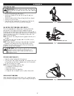
To release more line, lightly tap the bump knob on the ground (Fig. 7)
while operating the unit at high speed. For best results, tap the bump
knob on bare ground or hard soil. Attempting to release line in tall
grass may stall the engine.

NOTE:

Do not rest the cutting head on the ground while the unit is

running.

Each time the bump knob is tapped, about 1 inch (25.4 mm) of
trimming line is released. 

NOTE:

Always keep the trimming line fully extended. Line release

becomes more difficult when the cutting line gets shorter.

A blade in the cutting head shield will cut the line to the proper
length if any excess line is released.

HOLDING THE UNIT

Stand in the operating position (Fig. 6).

Hold the shaft grip with the right hand. Keep the right arm
slightly bent.

Hold the handle with the left hand. Keep the left arm straight.

Hold the unit at waist level.

Keep the cutting head parallel to the ground so that it easily
contacts the grass without the need for bending over.

WARNING:

Always wear eye, hearing, hand, foot and

body protection to reduce the risk of injury when operating
this unit.

CAUTION:

Do not remove or alter the line cutting blade

assembly. Excessive line length will make the unit
overheat. This may lead to serious personal injury or
damage to the unit.

TIPS FOR BEST RESULTS

Keep the cutting head parallel to the ground.

Cut from left to right whenever possible. This improves the unit's
cutting efficiency and throws clippings away from the operator.

Do not trim wet grass or weeds.

NOTE:

Some line breakage will occur from:

• Entanglement with foreign matter
• Normal line fatigue
• Attempting to cut thick vegetation
• Forcing the line into objects such as walls or fence posts

DECORATIVE TRIMMING

When trimming around trees, posts, fences, etc., rotate the whole
unit so that the cutting head is at a 30° angle to the ground (Fig. 8).

Fig. 6

Fig. 7

Fig. 8

Bump Knob

Summary of Contents for CS720

Page 1: ...r s Manual DO NOT RETURN THIS UNIT TO THE RETAILER PROOF OF PURCHASE WILL BE REQUIRED FOR WARRANTY SERVICE For assistance regarding the assembly controls operation or maintenance of the unit please ca...

Page 2: ...an well ventilated outdoor area where there are no sparks or flames DO NOT smoke Never operate the unit without the fuel cap securely in place Avoid creating a source of ignition for spilled fuel Wipe...

Page 3: ...jacketed extension cords approved for outdoor use Fig A Unit Power Cord Extension Cord OTHER SAFETY WARNINGS All service other than the maintenance procedures described in this manual should be perfo...

Page 4: ...can result in serious injury to the operator and or bystanders WEAR EYE AND HEARING PROTECTION WARNING Thrown objects and loud noise can cause severe eye injury and hearing loss Wear eye protection m...

Page 5: ...rees fences etc SPECIFICATIONS All specifications are based on the latest product information available at the time of printing We reserve the right to make changes at any time without notice Approxim...

Page 6: ...eld counterclockwise to align the hole on the cutting head shield with the hole on the mount bracket Fig 1 4 Insert the square bolt into the hole underneath the cutting head shield Fig 2 Push the squa...

Page 7: ...ise to tighten Fig 3 NOTE Do not tighten the nut Fig 4 For decorative edging with a string trimmer attachment lock the release button into the 90 edging hole Fig 3 Removing the Attachment 1 Turn the k...

Page 8: ...htly bent Hold the handle with the left hand Keep the left arm straight Hold the unit at waist level Keep the cutting head parallel to the ground so that it easily contacts the grass without the need...

Page 9: ...types of trimming line may cause the engine to overheat or fail NOTE Always use the correct line length when installing trimming line The line may not release properly if the line is too long Part 1 R...

Page 10: ...1 Cut one 6 foot 1 8 m length of new split line trimming line Split each end about 6 inches 150 mm 2 Using one split end insert one line into the top hole and the other line into the bottom hole in th...

Page 11: ...clean the unit and inspect it for any loose or damaged parts Repair or replace damaged parts and tighten loose screws nuts or bolts The cutting head is bound with grass Clean the cutting head The cutt...

Page 12: ...ossessions and territories except those sold through MTD s authorized channels of export distribution MTD reserves the right to change or improve the design of any MTD Product without assuming any obl...

Page 13: ...PAS CET APPAREIL CHEZ LE REVENDEUR UNE PREUVE D ACHAT SERA EXIG E POUR AVOIR RECOURS LA GARANTIE Pour obtenir de l aide concernant l assemblage les commandes l utilisation ou l entretien de cet appar...

Page 14: ...ons m ritent que vous les lisiez attentivement et les compreniez bien eux seuls les avertissements de s curit n liminent aucun danger Les consignes ou avertissements de s curit ne remplacent pas les m...

Page 15: ...ppareil et annuler votre garantie L appareil doit rester propre Retirez avec pr caution la v g tation et autres d bris qui pourraient bloquer les pi ces mobiles AVERTISSEMENTS DE S CURIT CONCERNANT LE...

Page 16: ...isation pour une information compl te sur la s curit l assemblage l utilisation l entretien et les r parations N entreposez jamais l appareil ayant encore du carburant dans le r servoir l int rieur d...

Page 17: ...cl tures etc SP CIFICATIONS L ensemble des sp cifications est bas sur les toutes derni res informations disponibles sur le produit l impression de ce manuel Nous nous r servons le droit d apporter des...

Page 18: ...pour aligner le trou de l cran de protection de la t te de coupe avec celui du support de montage Fig 1 4 Ins rez le boulon t te carr e dans le trou sous l cran de protection de la t te de coupe Fig...

Page 19: ...le serrer Fig 3 REMARQUE Ne pas serrer l crou Fig 4 Pour une bordure d corative r alis e avec un accessoire taille bordures verrouiller le bouton de d clenchement dans l orifice de bordure 90 Fig 3 D...

Page 20: ...e avec la main gauche Gardez le bras gauche bien droit Tenez l appareil hauteur de votre taille Gardez la t te de coupe parall le au sol de sorte qu elle entre facilement en contact avec l herbe sans...

Page 21: ...fe du moteur ou endommager le moteur REMARQUE Utilisez toujours la bonne longueur de ligne lorsque vous installez la ligne de coupe La ligne risque de ne pas se d rouler correctement si elle est trop...

Page 22: ...int rieur Enroulement d un fil Split Line 1 Coupez 1 8 m 6 pieds de fil Split Line neuf S parez chaque extr mit en deux sur environ 150 mm 6 po 2 En utilisant une extr mit fendue ins rez un fil dans...

Page 23: ...e m ticuleusement pour v rifier s il n y a pas de pi ces d tach es ou endommag es R parez ou remplacez les pi ces endommag es et serrez tous les boulons crous et vis desserr s La t te de coupe est eng...

Page 24: ...seau agr de distribution l exportation de MTD MTD se r serve le droit de modifier ou d am liorer la conception de ses produits sans pour autant assumer l obligation de modifier tout produit de fabrica...

Page 25: ...GIR COMPROBANTE DE COMPRA PARA LAS REPARACIONES Y EL MANTENIMIENTO QUE CUBRE LA GARANT A Por ayuda en relaci n con el montaje los controles el funcionamiento o el mantenimiento de la unidad llame al D...

Page 26: ...as de cualquier forma No opere la unidad si hay piezas flojas o da adas Inspeccione cuidadosamente el rea antes de encender la unidad Elimine todos los escombros y los objetos duros o filosos tales co...

Page 27: ...e vegetaci n u otros residuos que puedan bloquear las piezas m viles Si la unidad comienza a vibrar anormalmente det ngala de inmediato Inspeccione la unidad para encontrar la causa de la vibraci n Ge...

Page 28: ...seguridad No hacerlo puede ocasionar lesiones graves al operador y o a las personas presentes USE PROTECCI N PARA LOS OJOS Y O DOS ADVERTENCIA Los objetos lanzados y el ruido fuerte pueden ocasionar...

Page 29: ...NES Todas las especificaciones se basan en la informaci n del producto m s reciente disponible en el momento de la impresi n Nos reservamos el derecho de hacer cambios en cualquier momento sin previo...

Page 30: ...loj para alinear el orificio del protector del cabezal de corte con el orificio en el soporte de montaje Fig 1 4 Inserte el perno cuadrado en el orificio bajo el protector del cabezal de corte Fig 2 P...

Page 31: ...a ajustar Fig 3 NOTA No ajuste demasiado la tuerca Fig 4 Para un reborde decorativo con un accesorio de recorte trabe el bot n de liberaci n en el orificio de recorte de bordes de 90 Fig 3 Extracci n...

Page 32: ...con la mano izquierda Mantenga el brazo izquierdo recto Sujete la unidad a la altura de la cintura Sostenga el cabezal de corte paralelo al suelo de modo que haga contacto con la hierba f cilmente si...

Page 33: ...r a provocar recalentamiento o falla del motor NOTA Use siempre la longitud de l nea correcta al instalar la l nea de corte Es posible que la l nea no se suelte como es debido si es demasiado larga Pa...

Page 34: ...Line Separe cada extreme aproximadamente 6 pulgadas 150 mm 2 Con uno de los extremos divididos inserte un hilo dentro del orificio superior y otro hilo dentro del orificio inferior del carrete interi...

Page 35: ...macenamiento a largo plazo Limpie bien la unidad y compruebe que no haya piezas sueltas o da adas Repare o reemplace las piezas da adas y apriete los tornillos tuercas o pernos flojos El cabezal de co...

Page 36: ...36 NOTES...

Page 37: ...37 NOTES...

Page 38: ...38 NOTES...

Page 39: ...39 NOTES...

Page 40: ...rritorios excepto para aquellos vendidos a trav s de los canales autorizados de distribuci n de exportaciones de MTD MTD se reserva el derecho a cambiar o mejorar el dise o de cualquier Producto MTD s...

Reviews: