background image


26 

FITTING THE STABILITY BRACKET  

It is recommended that if the appliance is to be 
installed with a flexible supply pipe, a stability 
bracket be fitted and is available from your supplier 
(see Important Safety Requirements).  These 
instructions should be read in conjunction with any 
leaflet packed with the stability bracket. 


1.  Place the appliance in its intended position and 

level appliance. 

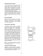
2.  Mark off 250mm from the left hand side of the 

appliance as shown in dimension 'A', Fig 4a.  
This is the centre line of the fixing bracket. 

3.  Draw a line from the front edge of the feet (see 

Fig.3a) and remove appliance from its position. 
Mark off dimension 'B' (see Fig.4a) back from 
this line on the centre line of the bracket to 
locate the front edge of the lower bracket.  Fix 
lower bracket (with two fixing holes) to the floor 
then measure the height from floor level to 
engagement edge on back of appliance, 
dimension 'C' of Fig. 4b. 

4.  Assemble upper bracket to lower bracket so that 

the underside of bracket is dimension 'C' + 3mm 
above floor level.  (See Fig. 4b) 
Reposition appliance and check that top bracket 
engages into appliance back as shown in Fig. 
4b. 


THE BATTERY 


1.  The battery is located at the front left hand side 

of the bottom storage compartment. 

2.  To gain assess to the battery, open the storage 

compartment and lift up the battery holder lid. 

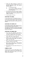
3.  Fit the new battery ensuring (+) terminal is next 

to the (+) sign on the battery.  See Fig. 5. 

4.  Close the lid of the battery holder. 


PRESSURE TESTING  


1.  The oven injector is used as a pressure test 

point. 

Remove the oven furniture.  Remove oven 
burner box retaining clips (one spring clip from 
each side) and remove box front cover.  Replace 
one clip back into the right hand side of the 
burner box.  Remove oven burner by removing 
the spring clip from the right hand side of the 
oven burner and slide burner off injector, whilst 
easing it forward and taking care not to strain the 
F.S.D. phial. 

2.  Connect the pressure gauge to the oven injector.   


Fig.5. 

Fig.4a.

Fig.4b.

(

A

)

(C)

100mm 

4

8

7

m

m

 (B) 

250mm 

20mm 

Summary of Contents for CC500

Page 1: ...HIGH LEVEL GRILL GAS COOKER CC500 1 PLEASE READ THIS INSTRUCTION BOOKLET BEFORE USING THE APPLIANCE OPERATING INSTALLATION INSTRUCTIONS ...

Page 2: ...trol system This appliance has been designed for domestic use to cook edible foodstuffs only and must not be used for any other purposes Take great care when heating fats and oils as they will ignite if they become too hot When you are lighting any burner check that it is lit before you leave the appliance When turning off a burner do not leave the appliance until the flame has gone out Never plac...

Page 3: ...Not Working 19 Service and Spare Parts 20 Guarantee Conditions 21 FOR THE INSTALLER Technical Details 22 Important Safety Requirements 23 Provision For Ventilation 23 Moving Your Appliance 24 For Your Safety 24 Location of Appliance 24 Levelling the Appliance 24 Grill Assembly 25 Connecting to Gas Supply 25 Fitting the Stability Bracket 26 The Battery 26 Testing 26 General Note 27 To help you the ...

Page 4: ...4 DESCRIPTION OF THE APPLIANCE GAS HIGH LEVEL GRILL WITH SINGLE OVEN RAPID OVEN NORMAL GRILL SIMMER NORMAL Country Cottage Storage Compartment Main Oven Control Panel Grill ...

Page 5: ...5 GETTING TO KNOW YOUR APPLIANCE THE CONTROL PANEL FEATURES A Ignition Switch B Hotplate Controls C Grill Control D Main Oven Temperature Control E Hotplate Controls A B C D E 1 9 S 8 7 9 5 4 3 2 ...

Page 6: ...efore advisable to open a window for ventilation CONDENSATION AND STEAM When food is heated it produces steam similar to a boiling kettle The vents allow some of this steam to escape However always stand back from the appliance when opening the door s to allow any build up of steam or heat to release If the steam comes into contact with a cool surface on the outside of the appliance e g a trim it ...

Page 7: ... supports are correctly fitted before using the hob TO LIGHT THE HOB BURNERS The hob ignition works by means of a battery Push in and turn the control knob to the left to the highest setting This is shown by a large flame symbol Press the ignition button immediately When the burner has lit release the control and ignition button adjust the setting as required Warning If the ignition button is not ...

Page 8: ...Do not slide them across the hob Do not leave accidental spillage on the hob or removable parts The spillage should be wiped up and the parts washed and carefully dried as soon as the hob pan supports and burner parts are cool enough to touch A flat based Wok will stand stable on the pan supports If you use a round Wok with a collar support the collar must be the open wirework type otherwise the p...

Page 9: ...ol highest setting Press the ignition button immediately When the burner has lit release the control and ignition button adjust the setting as required THINGS TO NOTE Some smoke from fat splashes may be evident as the grill cleans itself Never cover the grill pan or grid with foil as this can lead to grill fires THE GRILL PAN AND HANDLE The grill pan requires assembly before use see Fig 1 Ensure t...

Page 10: ...rid in the high position Preheat the grill on a full setting for a few minutes before sealing steaks or toasting Adjust the heat setting as necessary during cooking The food should be turned over during cooking as required GRILLING CHART FOOD POSITION GRILL TIME mins in total Bacon Rashers 5 6 Beefburgers 10 15 Chicken Joints 30 40 Chops Lamb 15 20 Pork 20 30 Fish Whole Trout Mackerel 15 25 Fillet...

Page 11: ...utes For recipes needing high temperatures e g bread pastries scones soufflés etc best results are achieved if the oven is preheated first For best results when cooking frozen or cooked chilled ready meals always preheat the oven first USING THE MAIN OVEN Open the oven door Push in the control knob and turn it to gas mark 9 When the burner has lit release the button There will only be small flames...

Page 12: ...nd give less base browning When cooking more than one dish in the oven place dishes centrally on different shelves rather than cluster several dishes on one shelf this will allow the heat to circulate freely for the best cooking results If you are cooking more than one tray of similar items for example cakes or biscuits swap the trays during cooking or you can remove the top tray when the food is ...

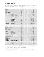
Page 13: ...ufacturer s instructions Fish 2 4 20 30 Fish Pie Potato Topped 3 6 20 25 Fruit Pies Crumbles 3 6 40 50 Milk Puddings 3 2 1 2h Pasta Lasagne etc 3 5 30 40 Pastry Choux Eclairs Profiteroles Flaky Puff Pies Shortcrust Mince Pies Meat Pies Quiche Tarts Flans 2 2 2 1 3 2 2 6 5 6 5 7 5 30 35 20 30 25 40 15 20 25 35 25 45 Roasting Meat Poultry 4 5 see roasting chart Scones 1 3 7 8 12 Shepherd s Pie 3 7 3...

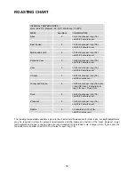
Page 14: ...s over Turkey and Goose 5 20 25 minutes per kg 1lb up to 3 kg 7lb then 10 minutes per kg 1lb over 3 kg 7lb Duck 5 25 35 minutes per kg 1lb and 25 30 minutes over Pheasant 5 35 40 minutes per kg 1lb and 35 40 minutes over Rabbit 5 20 minutes per kg 1lb and 20 minutes over The roasting temperatures and times given in the chart should be adequate for most joints but slight adjustments may be required...

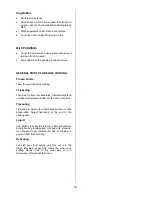
Page 15: ...start the food cooking FOOD PREPARATION SLOW COOKING JOINTS OF MEAT AND POULTRY Do not cook meat joints over 2 7kg 6lb Do not cook poultry over 2 kg 4lb 8oz Cook on the middle shelf of the oven or above Cook stuffing separately Cook for at least six hours Only cook joints of pork if you can make sure by using a meat thermometer that the temperature inside the joint is at least 88 C For good air ci...

Page 16: ... cooking Thickening Toss meat in flour for casseroles Alternatively blend cornflour with water and add it at the end of cooking Flavouring Flavours are held in the food because there is little evaporation Adjust flavouring at the end of the cooking time Liquid Use slightly less liquid as there is little evaporation during cooking Always add milk and milk products for example cream towards the end ...

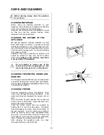
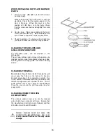
Page 17: ...pt to remove any of the control knobs from the appliance as this may cause damage and is a safety hazard CLEANING THE CONTROL KNOBS AND HANDLES It is strongly recommended that only hot soapy water is used for cleaning the control knobs and handles ANY OTHER CLEANING MATERIALS MAY DULL THE SURFACE FINISH CLEANING THE HOB Clean the hotplate top using a mild abrasive Take care not to damage the spark...

Page 18: ...grill pan grill pan grid and oven shelves may be cleaned using a soap impregnated steel wool pad Soaking first in hot soapy water will make cleaning easier CLEANING THE GRILL Do not clean the grill burner itself Cleaning the grill may cause the holes in the burner to become blocked preventing it from operating correctly Due to the nature of stainless steel the grill burner may tarnish through use ...

Page 19: ...emperatures and shelf positions are being used The oven temperature is too high or too low Check that the recommended temperatures and shelf positions are being used Be prepared to adjust the temperature up or down slightly to achieve the results you want Ensure the burner parts have been placed correctly The battery may need replacing The hob burners will not light Check that there is not a probl...

Page 20: ...e Service Force Centre you will need to give the following details 1 Your name address and post code 2 Your telephone number 3 Clear and concise details of the fault 4 The model and serial number of the appliance found on the rating plate 5 The purchase date Please note that a valid purchase receipt or guarantee documentation is required for in guarantee service calls CUSTOMER CARE DEPARTMENT For ...

Page 21: ...ss or plastic Costs incurred for calls to put right an appliance which is improperly installed or calls to appliances outside the United Kingdom Appliances found to be in use within a commercial environment plus those which are subject to rental agreements Products of Tricity Bendix manufacture which are not marketed by Tricity Bendix European Guarantee If you should move to another country within...

Page 22: ...Volt AA size HOTPLATE Natural Gas Heat Input R H F R H R L H R L H F 1 0kW 1 9kW 2 0kW 2 8kW 3412 Btu h 6483 Btu h 6483 Btu h 9895 Btu h Injector Marking 070 096 096 119 L P Gas Heat Input 1 0kW 1 9kW 1 9kW 2 8kW 71 8g h 136 5g h 136 5g h 194 0g h Injector Marking 050 071 71 086 GRILL Natural Gas L P Gas Heat Input 3 0kW 10236 Btu h 2 75kW 197 5g h Injector Marking 120 080 MAIN OVEN Heat Input 2 4...

Page 23: ... on the back or top of some models where applicable Do not alter the electrical circuitry of this appliance PROVISION FOR VENTILATION This appliance is not connected to a combustion products evacuation device It shall be installed and connected in accordance with the current installation regulations Particular attention shall be given to the relevant requirements regarding ventilation The room con...

Page 24: ... or garage It is essential that the appliance is positioned as Fig 1 The appliance must be a minimum of 20mm from the rear wall note that this dimension is provide by the inlet elbow Shelves wall cabinets and cooker hoods must not be fitted closer than 500mm to the top of the grill canopy or within 100mm of the sides of the grill Curtains must not be fitted immediately behind the appliance or with...
Page 25: ...appliance flexible connection only Supply piping should not be less than R3 8 Connection is made to the Rc B S P female threaded entry pipe located just below the hotplate level on the rear left hand side of the appliance NOTE ONLY LIQUID SEALANTS TO BE USED WHEN INLET GAS PIPE IS FITTED I E DO NOT USE P T F E SEALANT TAPE Carry out a gas tightness test after connecting to the gas supply The gas b...

Page 26: ...C of Fig 4b 4 Assemble upper bracket to lower bracket so that the underside of bracket is dimension C 3mm above floor level See Fig 4b Reposition appliance and check that top bracket engages into appliance back as shown in Fig 4b THE BATTERY 1 The battery is located at the front left hand side of the bottom storage compartment 2 To gain assess to the battery open the storage compartment and lift u...

Page 27: ...pan supports Check each of the hotplate burners in turn by turning the hotplate tap to its full on position and pressing the ignition button As soon as the burners are lit the button can be released CHECKING THE MAIN OVEN 1 Turn on the oven thermostat control knob to mark 9 and press the ignition button As soon as the burner is alight the button can be released 2 There should now be a low gas rate...

Page 28: ...PORTANT NOTICE In line with our continuing policy of research and development we reserve the right to alter models and specifications without prior notice This instruction booklet is accurate at the date of printing but will be superseded if specifications or appearance are changed CC500 1 311756500 Electrolux plc 2005 ...

Reviews: