background image

QUICK START GUIDE

FMS-1655 Quick Start Guide

FMS-1655

38

 -

Introduction

Following the proper installation of the FMS-

1655, apply power to the unit and confirm 

that you hear a brief chirp at the touchscreen 

display, which indicates that the display 

module is communicating with the controller 

module. Upon power up, the Safety Halo

TM 

status indication bezel will cycle through 

seven colors (red, green, blue, yellow, 

magenta, cyan, and white) followed by three 

action icons (normal, caution, alarm), and 

finally the Triatek splash screen will remain 

displayed for approximately 10 seconds and 

will then disappear to reveal the main display 

screen. 

NOTE: The information displayed on the 

splash screen during the power up sequence 

may also be redisplayed using the About This 

FMS option on the Diagnostics menu.

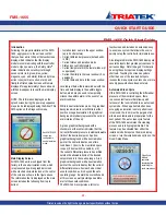
Main Display Screen

All FMS-1655 units are shipped from the 

factory in the neutral isolation mode, which 

is represented by a blue graphical screen 

with a slashed circle status icon at the center 

of the screen as shown in the figure above. 

The information that is displayed on the main 

screen includes the following from top to 

bottom:

•  Isolation room name in the upper window 

(up to 24 characters)

•  Current differential pressure (default units: 

in WC)

•  Current status and isolation mode 

•  Status icon centrally located

•  Current temperature in the lower window (if 

so equipped)

•  Current humidity in the lower window (if so 

equipped)

•  Current time and date in the lower window 

Located just below the lower window with the 

time and date display is the audible toggle 

button, which may be used to temporarily 

silence the audible alarm in the event of an 

alarm condition. 

While in neutral isolation mode, the graphical 

background is blue in color. While in either 

positive or negative isolation, the graphical 

background intuitively represents the current 

alarm status of the unit. 

A green graphical background with a 

checkmark at the center indicates that the 

current differential pressure is within allowable 

limits of the desired setpoint. A yellow 

graphical background with an exclamation 

point at the center indicates one of two 

conditions: 1) door to the monitored space 

is open (if door switch is enabled), or 2) 

the current differential pressure has drifted 

outside the allowable limits of the desired 

setpoint and is in the caution range. A red 

graphical background with an exclamation 

point at the center indicates that the current 

differential pressure has reached a critical 

unsafe condition, as it is beyond the safe 

operating range. An alarm buzzer will sound 

at this screen as well providing an audible 

alert of the unsafe conditions.

The FMS-1655 incorporates a full-color 

touchscreen and includes an extensive easy-

to-use menu system that allows the user to 

quickly setup the controller for immediate use.

Also integrated into the FMS-1655 display are 

several hotspots that provide quick access to 

various settings. Refer to page 51 for details 

on using these hotspots as display settings 

shortcuts. Touching the screen anywhere 

other than one of the reserved hotspots 

invokes the menu system, unless one or more 

security passwords have been entered.

Automated Clean Cycle

If this FMS-1655 is controlling the differential 

pressure of the monitored space, there 

is a convenient feature that allows quick 

turnover of the room referred to as auto clean 

cycle mode. When a patient who has been 

occupying an isolation room or patient room 

is removed, the room must be purged of all 

airborne contaminants in preparation for the 

next patient. The auto clean cycle feature 

of the FMS-1655 automates this cleaning 

process and is fully programmable. This 

feature may be activated from either the 

isolation mode hotspot on the main display 

screen, or via the isolation mode option on the 

Room Setup Menu.

Triatek reserves the right to change product specifications without notice.

Each FMS-1655 

comes pre-

configured in 

neutral isolation 

mode.

Clean Cycle 

Mode in 

operation 

displaying time 

remaining for 

cycle completion.

Summary of Contents for FMS-1655

Page 1: ...FMS 1655 Installation Manual Version 11 15 16 Triatek FMS 1655 Room Pressure Controller ...

Page 2: ...FMS 1655 Triatek reserves the right to change product specifications without notice Notes ...

Page 3: ...to follow the wiring diagrams could result in damage to your equipment and could void your warranty Wiring diagrams can also be found at www triatek com Under no circumstances should a single transformer be split between actuator and controller Doing so will damage the actuator the transformer the controller or all units A single 120 24V 30Va transformer is required for the controller and a separa...

Page 4: ...ange zero based or offset Sensor Pressure Range Positive Isolation Setpoint Negative Isolation Setpoint Neutral Isolation Setpoint Pressure Deadband Analog Output Operating Mode Direct or PID Analog Output Range zero based or offset Analog Output Upper Limit 0 100 Analog Output Lower Limit 0 100 Analog Output Input Channel AI 1 thru AI 4 TI 1 or TI 2 Analog Output Action Direct or Reverse Analog O...

Page 5: ... Isolation High Warning Setpoint Positive Isolation Low Warning Setpoint Positive Isolation Low Alarm Setpoint Negative Isolation High Alarm Setpoint Negative Isolation High Warning Setpoint Negative Isolation Low Warning Setpoint Negative Isolation Low Alarm Setpoint Audible Alert Enabled Input Channels AI 1 thru AI 4 TI 1 TI 2 Operating Mode audible or silent Delay Time Base secs or mins Delay S...

Page 6: ...stration 21 Analog Input to 2 Remote Pressure Sensors 0 10V Out Illustration 22 Analog Input to 2 Remote Pressure Sensor 4 20mA Out Illustration 23 Analog Input to 3 Remote Pressure Sensor 4 20mA Out Illustration 24 Analog Input to 4 Remote Pressure Sensor 4 20mA Out Illustration 25 Analog Input to Temperature Sensor Illustration 26 Digital Input to Door Switch Illustration 28 Digital Input to Flo...

Page 7: ...net OBJECTS Analog Input Objects 48 Analog Output Objects 48 Binary Input Objects 48 Binary Output Objects 48 Analog Value Objects 48 49 Multistate Output Objects 49 METASYS N2 OBJECTS Analog Input Objects 50 Analog Output Objects 50 Binary Input Objects 50 Binary Output Objects 50 Internal Float Value Objects 50 51 Multistate Output Objects 51 CLEANING THE DISPLAY Cleaning the FMS 1655 53 DIAGRAM...

Page 8: ...s N2 network Two Wire Twisted Pair RS 485 signaling Recommended Cable Type Belden 3107A Touchscreen User Interface LCD Size 3 2 diagonal LCD Type Transmissive Resolution 240 x 320 portrait Viewing Area 50 60 mm x 66 80 mm Color Depth 18 bit or 262K colors Backlight Color White Luminous Intensity Min 2500 cd m2 Recommended Cable Type applicable to surface mount models FMS 1655 s x only Belden 3125A...

Page 9: ...n warns that changes or modifications to the unit not expressly approved by the part responsible for compliance could void the user s authority to operate the equipment This device complies with Part 15 of the FCC Rules Operation is subject to the following two conditions This device may not cause harmful interference and This device must accept any interference received including interference tha...

Page 10: ... very intuitive and simplifies the setup and configuration of the unit The menus incorporate touch based interfaces such as sliders radio buttons and dialog popups to facilitate the ease of use of the FMS 1655 The display implements bright graphical color changes to indicate the three different alarm status indications of the monitored isolation room These graphical backgrounds indicate Normal whe...

Page 11: ...nel may have unrestricted access while general staff may be assigned restricted access passwords which limit the functionality of the user menus Room pressure selection of positive negative or neutral isolation may be protected using limited access passwords thereby eliminating the need for keylock switches and keys An optional keylock switch may be used to further control access to change in isol...

Page 12: ...hscreen is easily accessible to facilitate silencing the unit in the event of an alarm The FMS 1655 is pre configured at the factory with the Safety Halo status indicator bezel connected to the internal circuitry on the display board and has been tested for proper operation The Safety Halo should not be removed from the flush mount faceplate as it may damage the internal circuitry and or the bezel...

Page 13: ...opriate hardware 8 Mount the louvered stainless steel cover plate to the mounting plate with the screws supplied 9 Apply power to the FMS 1655 and confirm that following a brief initialization sequence the unit displays the room differential pressure and the Safety Halo status matches that of the main display screen FMS 1655 units are shipped from the factory in neutral isolation mode MOUNTING WIR...

Page 14: ...ttings programmed in the factory according to the customer specifications The user can change the settings by using the instructions provided in the Quick Start section of this manual beginning on page 38 Triatek reserves the right to change product specifications without notice ...

Page 15: ... 8 FMS 1655 MOUNTING WIRING Triatek reserves the right to change product specifications without notice Notes Triatek reserves the right to change product specifications without notice ...

Page 16: ...inal hole dimensions are 3 65 H x 2 15 W 2 Drill a 7 16 hole through the opposite wall for the flow tube as shown 3 Bring the 3 conductor signal wire through the cut out 4 Install the included low voltage mounting bracket in the drywall opening and pull the 3 conductor signal cable through the mounting bracket 5 Push a length of flow tube through the back hole on through the 7 16 hole in the oppos...

Page 17: ...ply around tube and between stainless steel plate and wall to seal unit penetration Terminal For connection of transmitter to FMS 1655 Flow Tube When Flow Tube mounting plate is located directly opposite the sensor flow tubing must be cut as short as possible to prevent kinks To FMS 1655 Controller Wall Section cutaway view Orange wall bracket to be installed first by using the rotating clamps for...

Page 18: ...ounting Plate Gasket Thin Silicone Caulking apply around tube and between stainless steel plate and wall to seal unit penetration Terminal For connection of transmitter to FMS 1655 Flow Tube When Flow Tube mounting plate is located directly opposite the sensor flow tubing must be cut as short as possible to prevent kinks To FMS 1655 Controller Wall Section cutaway view Rotating clamps secure assem...

Page 19: ...s the line voltage or other conductors that supply highly inductive loads such as generators motors solenoids contactors etc Use 22AWG or larger MOUNTING WIRING Triatek reserves the right to change product specifications without notice Remote Sensor Configuration Controller Configuration Dipswitch Settings S1 1 ON S1 5 OFF AI 1 set at 4 20mA Input Recommended 4 conductor connection Belden 1325A St...

Page 20: ... to change product specifications without notice Analog Output to Electric Damper Actuator Controller Configuration Dipswitch Settings S1 2 ON S1 6 OFF AI 2 set as 4 20mA Input S4 1 ON AO 1 set as Voltage Output Step Down Isolation Transformer provided with FMS Controller ...

Page 21: ...roduct specifications without notice Analog Output to Pneumatic Damper Actuator Controller Configuration Dipswitch Settings S1 2 ON S1 6 OFF AI 2 set as 4 20mA Input S4 1 ON AO 1 set as Voltage Output Step Down Isolation Transformer provided with FMS Controller Optional remote sensor ...

Page 22: ...e product specifications without notice Analog Output to Variable Speed Drive Controller Configuration Dipswitch Settings S1 2 ON S1 6 OFF AI 2 set as 4 20mA Input S4 1 ON AO 1 set as Voltage Output Step Down Isolation Transformer provided with FMS Controller Optional remote sensor ...

Page 23: ...uct specifications without notice Analog Output to Modulated Air Controller Controller Configuration Dipswitch Settings S1 2 ON S1 6 OFF AI 2 set as 4 20mA Input S1 4 ON S1 8 OFF AI 4 set as 4 20mA Input Step Down Isolation Transformer provided with FMS Controller Optional remote sensor ...

Page 24: ... to change product specifications without notice Analog Output to Pneumatic Damper Actuator Controller Configuration Dipswitch Settings S1 1 ON S1 5 OFF AI 1 set as 20mA Input S4 1 ON AO 1 set as Voltage Output Step Down Isolation Transformer provided with FMS Controller ...

Page 25: ...ht to change product specifications without notice Analog Output to Variable Speed Drive Controller Configuration Dipswitch Settings S1 1 ON S1 5 OFF AI 1 set as 20mA Input S4 1 ON AO 1 set as Voltage Output Step Down Isolation Transformer provided with FMS Controller ...

Page 26: ...ge product specifications without notice 19 Controller Configuration Dipswitch Settings S1 2 ON S1 6 OFF AI 2 set as 4 20mA Input Adding Remote Pressure Sensor with 4 20mA Out to Internal Sensor Model Step Down Isolation Transformer provided with FMS Controller ...

Page 27: ...MOUNTING WIRING FMS 1655 Triatek reserves the right to change product specifications without notice 20 Notes ...

Page 28: ...pecifications without notice 21 Controller Configuration Dipswitch Settings S1 1 ON S1 5 OFF AI 1 set as 4 20mA Input S1 2 ON S1 6 OFF AI 2 set as 4 20mA Input Analog Input to 2 Remote Pressure Sensors 4 20mA Out Step Down Isolation Transformer provided with FMS Controller ...

Page 29: ...onfiguration Dipswitch Settings S1 1 ON S1 5 OFF AI 1 set as 4 20mA Input S1 2 ON S1 6 OFF AI 2 set as 4 20mA Input S1 3 ON S1 7 OFF AI 3 set as 4 20 mA Input Triatek reserves the right to change product specifications without notice Step Down Isolation Transformer provided with FMS Controller ...

Page 30: ...nge product specifications without notice Controller Configuration Dipswitch Settings S1 1 ON S1 5 OFF AI 1 set as 4 20mA Input S1 2 ON S1 6 OFF AI 2 set as 4 20mA Input S1 3 ON S1 7 OFF AI 3 set as 4 20 mA Input S1 4 ON S1 8 OFF AI 4 set as 4 20 mA Input Step Down Isolation Transformer provided with FMS Controller ...

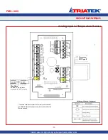
Page 31: ...specifications without notice 24 Analog Input to Temperature Sensor The above example associates the Thermistor with contacts T1 and AGND for illustrative purposes only In fact either of the two T s can be used Step Down Isolation Transformer provided with FMS Controller ...

Page 32: ...ote Sensor FMS 1655 25 Triatek reserves the right to change product specifications without notice Controller Configuration Dipswitch Settings S1 2 OFF S1 6 ON AI 2 set as 0 10V Input Step Down Isolation Transformer provided with FMS Controller ...

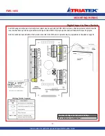
Page 33: ...0 may be purchased from Triatek for this specific purpose After the switch has been installed at the door and connected to the FMS unit its operation may be programmed as described on page 39 Controller Configuration Slideswitch Settings S5 Left Active Low Digital Input Digital Input to Door Switch Triatek reserves the right to change product specifications without notice Step Down Isolation Trans...

Page 34: ...SUBHEAD FMS 1655 27 MOUNTING WIRING Triatek reserves the right to change product specifications without notice Notes ...

Page 35: ...al Input to Occupancy Sensor Triatek reserves the right to change product specifications without notice The above example associates the Occupancy Sensor with contacts DI4 and DGND for illustrative purposes only In fact any of the four DI s can be used Step Down Isolation Transformer provided with FMS Controller ...

Page 36: ...ecifications without notice Relay Output to Alarm The above example associates Monitor Output 1 with contacts RL3 and RL3_C for illustrative purposes only In fact any of the four RL s and the corresponding RL _C can be used Step Down Isolation Transformer provided with FMS Controller ...

Page 37: ...o change product specifications without notice The above example associates Monitor Output 2 with contacts RL4 and RL4_C for illustrative purposes only In fact any of the four RL s and the corresponding RL _C can be used Step Down Isolation Transformer provided with FMS Controller ...

Page 38: ...t specifications without notice Relay Output 1 The above example associates Heating State 1 with contacts RL1 and RL1_C for illustrative purposes only In fact any of the four RL s and the corresponding RL _C can be used Step Down Isolation Transformer provided with FMS Controller ...

Page 39: ...ange product specifications without notice The above example associates Heating State 2 with contacts RL2 and RL2_C for illustrative purposes only In fact any of the four RL s and the corresponding RL _C can be used Step Down Isolation Transformer provided with FMS Controller ...

Page 40: ...SUBHEAD FMS 1655 33 MOUNTING WIRING Triatek reserves the right to change product specifications without notice Power Step Down Isolation Transformer provided with FMS Controller ...

Page 41: ...rovided with FMS 1655 Only Class 2 wiring in this compartment Note This product should be installed with the manufacturer provided isolated power supply and connected to an electrical circuit protected by a minimum 20A circuit breaker This circuit breaker should be mounted in an approved electrical enclosure located separately but in close proximity to this product 240 VAC 50 60 Hz Blue 1 Amp Slow...

Page 42: ...SUBHEAD FMS 1655 35 MOUNTING WIRING Triatek reserves the right to change product specifications without notice Notes ...

Page 43: ...ht to change product specifications without notice Controller Configuration Dipswitch Settings S3 7 ON S3 8 ON BACnet MS TP protocol selected NOTE For optimum network communications the reference signal REF must be connected to the BMS NETWK REF terminals at the backplane ...

Page 44: ...ON S3 8 OFF Metasys N2 Open protocol selected COMMUNICATIONS Metasys N2 Open Triatek reserves the right to change product specifications without notice NOTE For optimum network communications the reference signal REF must be connected to the NETWK REF terminals at the backplane ...

Page 45: ...ckmark at the center indicates that the current differential pressure is within allowable limits of the desired setpoint A yellow graphical background with an exclamation point at the center indicates one of two conditions 1 door to the monitored space is open if door switch is enabled or 2 the current differential pressure has drifted outside the allowable limits of the desired setpoint and is in...

Page 46: ...p Analog Output and the user is prompted to select an operating mode direct control or PID control and an operating range Most applications will take advantage of the PID proportional integral derivative control mode where the control output can be customized by varying the control loop constants The operating range can either include an offset from zero or not independent of whether the analog ou...

Page 47: ...des Changing the mode of isolation automatically selects the pre programmed setpoints and alarm limits associated with each mode Invoking Auto Clean Cycle When an isolation room has been vacated it must be cleaned of all airborne contaminants before the next patient may occupy the room The FMS 1655 includes a convenient feature called Auto Clean Cycle that automates the turnover process and cleani...

Page 48: ...ID control loop if enabled Cancelling the override effectively resumes the normal PID control loop operation again if enabled A unique feature of the FMS 1655 is the Real Time View option which allows the user to see in real time the actual inputs and outputs along with their voltage levels or states One of the most useful tools for fine tuning the PID loop performance is the Analog I O Pairs scre...

Page 49: ...FMS 1655 42 QUICK START GUIDE Notes Triatek reserves the right to change product specifications without notice ...

Page 50: ...itch S2 mode configuration 1 1 Product Type OFF FMS HMS ON CMS 1655 2 Remote Display OFF Disabled ON Enabled 3 Mode Select OFF FMS 1655 CMS 1655 ON HMS 1655 4 Operational Mode OFF Demo Mode ON Run Mode Pushbutton Switch SW1 Reset Button Pushbutton Switch SW2 Reserved SUBHEAD FMS 1655 43 MODULE SETTINGS Triatek reserves the right to change product specifications without notice Configuring Display M...

Page 51: ...tion 5 to OFF To configure FMS 1655 for a remote sensor set dipswitch position 1 to ON and dipswitch position 5 to OFF For other inputs see Table 1 Analog Output Configuration Dipswitch S3 1 AO 1 Mode Selection OFF current output ON voltage output 2 AO 2 Mode Selection OFF current output ON voltage output 3 AO 3 Mode Selection OFF current output ON voltage output 4 AO 4 Mode Selection OFF current ...

Page 52: ...2 Protocol Selection Settings S3 Protocol Selection S3 7 S3 8 Reserved OFF OFF Metasys N2 ON OFF BACnet MS TP default ON ON Controller Configuration Dipswitch S4 1 AO 1 Voltage Range Selection OFF 0 10Vdc ON 0 5Vdc 2 AO 2 Voltage Range Selection OFF 0 10Vdc ON 0 5Vdc 3 AO 3 Voltage Range Selection OFF 0 10Vdc ON 0 5 Vdc 4 AO 4 Voltage Range Selection OFF 0 10Vdc ON 0 5 Vdc Controller Configuration...

Page 53: ...gital input Read Only Binary Outputs BO 1 Relay Output 1 default Primary Alarm Relay Output Read Only BO 2 Relay Output 2 default Secondary Alarm Relay Output Read Only BO 3 Relay Output 3 spare relay output Read Only BO 4 Relay Output 4 spare relay output Read Only Analog Values AV 1 AI 1 Setpoint Isolation Room Differential Pressure Read Write AV 2 AI 2 Setpoint Anteroom Differential Pressure Re...

Page 54: ...AV 41 TI 2 High Warning Setpoint Read Write AV 42 TI 2 High Alarm Setpoint Read Write AV 43 Writable Network Variable Humidity Read Write AV 44 Writable Network Variable Temperature Read Write AV 45 Writable Network Variable Air Changes Read Write AV 46 Writable Network Variable Differential Pressure Read Write AV 47 Device ID Offset range 0 4 194 000 Read Write AV 48 Duct Air Flow based on AI 1 f...

Page 55: ... Read Only Internal Float Values ADF 1 PID Control Loop 1 Setpoint Primary Differential Pressure Read Write ADF 2 Primary Room Alarm Relay High Setpoint Read Write ADF 3 Primary Room Alarm Relay Low Setpoint Read Write ADF 4 Secondary Room Alarm Relay High Setpoint Read Write ADF 5 Secondary Room Alarm Relay Low Setpoint Read Write ADF 8 Primary Room Low Alarm Setpoint Read Write ADF 9 Primary Roo...

Page 56: ... 49 Air Flow based on Flow Input at AI 2 Read Only ADF 50 Air Flow based on Flow Input at AI 3 default Supply Flow Read Only ADF 51 Air Flow based on Flow Input at AI 4 default Exhaust Flow Read Only ADF 52 Volumetric Offset Supply Flow Exhaust Flow Read Only ADF 53 Volumetric Offset Setpoint Read Write ADF 54 AO 1 Override Level Read Write ADF 55 AO 2 Override Level Read Write ADF 56 AO 3 Overrid...

Page 57: ...FMS 1655 50 Notes Triatek reserves the right to change product specifications without notice ...

Page 58: ... the monitored room Touching the current displayed pressure reading brings up the secondary pressure reading if the unit is in dual sensor mode Touching anywhere else on the screen enters the Main Setup Menu if no password is stored Otherwise a password must be entered before the Main Setup Menu can be accessed Touching DATE brings up the Date Entry popup to quickly change the current displayed da...

Page 59: ...ve Wiring Diagram FMS 1655 52 Triatek reserves the right to change product specifications without notice Recommended 4 conductor connection Belden 3107A Step Down Isolation Transformer provided with FMS Controller ...

Page 60: ...Integrated Flush Mount Wiring Box Dimensions FMS 1655 53 Triatek reserves the right to change product specifications without notice ...

Page 61: ...Flush Mount Bracket Dimensions FMS 1655 54 Triatek reserves the right to change product specifications without notice ...

Page 62: ...Thin Mount Wiring Box Dimensions FMS 1655 55 Triatek reserves the right to change product specifications without notice ...

Page 63: ...Notes FMS 1655 56 Triatek reserves the right to change product specifications without notice ...

Page 64: ...FLOW DIAGRAMS FMS 1655 57 Unit Setup Menu Tree Triatek reserves the right to change product specifications without notice ...
Page 65: ...FLOW DIAGRAMS System Setup Menu Tree FMS 1655 58 Triatek reserves the right to change product specifications without notice ...
Page 66: ...System Setup Menu Tree FLOW DIAGRAMS FMS 1655 Triatek reserves the right to change product specifications without notice 59 ...

Page 67: ...FLOW DIAGRAMS FMS 1655 60 System Setup Menu Tree Triatek reserves the right to change product specifications without notice ...

Page 68: ...FMS 1655 Due to continuous improvement Triatek reserves the right to change product specifications without notice 61 Display Setup Menu Tree Triatek reserves the right to change product specifications without notice ...

Page 69: ...FLOW DIAGRAMS FMS 1655 62 Diagnostics Menu Tree Triatek reserves the right to change product specifications without notice ...
Page 70: ...rs sensors actuators and more all designed to seamlessly integrate into a facility s building automation system Laboratories Classrooms Vivariums Hospitals Triatek s customer service is unparalleled Our product support system includes on site installations phone support repairs calibrations and in depth training sessions From our knowledgeable engineers and sales team to our talented field technic...

Reviews: