TriangleTube PRESTIGE Excellence PSRKIT01 Manual Download Page 4

PRESTIGE Excellence

HX Field Replacement

Kit 

4

1. Remove both top access panels located above

the heat exchanger and water heater on the top

jacket panel.

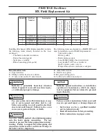
2.  Remove ignition cable and green ground wire

from the igniter. (Fig. 4).

3.  Disconnect the ignition cable from the MCBA

control module and remove air intake pipe from

venturi.  (Shown as item 2 in Fig 1).  Place the

intake pipe and ignition cable aside, DO NOT

discard as they will be re-used.

4.  Disconnect the electrical connection(s) for the

blower at the blower housing.  

5.  Remove the mounting screw and disconnect the

black rectifier  plug from the gas valve.

6.  Disconnect  the  grey  flat  ribbon  cable  from  the

display board at the MCBA control module.  

7. Disconnect the orange low voltage and high volt-

age wiring terminal strips by unplugging the bot-

tom strips from the upper portion.

8. Remove the retaining screw for control mount-

ing panel and swing open the control mounting

panel.  The high voltage and low voltage termi-

nals  should  pass  through  the  lower  cutouts  of

the panel to allow movement of the panel.

9.  Disconnect the red wire leads from supply tem-

perature  sensor  (Shown  as  item  3  in Fig.  1)

located at the top of the heat exchanger. 

10.  Disconnect the blue wire leads from return tem-

perature  sensor  (Shown  as  item  4  in Fig.  1)

located at the bottom of the heat exchanger.

11. Disconnect the orange wire leads from the Low

Water  Cut-Off  (LWCO)  pressure  switch

(Shown as item 5 in Fig. 1). Use care when dis-

connecting the wire leads as not to damage the

LWCO terminals or the wire leads.

Removal of Electrical Connections (TriMax)

Before disconnecting any wire connections mark and

label all connections and locations of the connections.

1. Remove both top access panels located above

the heat exchanger and water heater on the top

jacket panel.

2.  Slide left and right tabs of control panel inward

and lower control panel.

3.  Pull the retaining tabs on top of the rear cover to

remove the rear control box cover.

4.  Remove green ground wire from the igniter and the

ignition cable from the TriMax control module.

5.  Remove air intake pipe (Shown as item 2 in Fig.

1) from venturi.  Place the intake pipe aside, DO

NOT discard as it will be re-used.

6.  Disconnect the electrical connection(s) for the

blower at the blower housing.

7.  Disconnect the Molex plug from the gas valve.

8.  Disconnect  the  Molex  plug  from  supply  tem-

perature  sensor  (Shown  as  item  3  in  Fig.  1)

located at the top of the heat exchanger.

NOTICE

Ignition 

Cable

Igniter

Venturi

Fig. 4: Top of Heat Exchanger

Summary of Contents for PRESTIGE Excellence PSRKIT01

Page 1: ...1 PSRKIT01 Heat Exchanger Assembly X 1 PTRKIT124 Heat Exchanger Assembly X 1 PSRKIT76 Heat Exchanger Assembly X 1 PTRKIT125 Heat Exchanger Assembly X Indicates a potentially hazardous situation which...

Page 2: ...Attach a hose to external boiler drain Place other end of this hose to a suitable drain 8 Open external boiler drain valve and begin draining the boiler To assist in the draining of the boiler remove...

Page 3: ...d from the boiler it should be inspected for deformation damage or corrosion If there are any signs of deformation damage or corrosion on the vent outlet adapter replace it immediately Check condition...

Page 4: ...ated at the top of the heat exchanger 10 Disconnect the blue wire leads from return tem perature sensor Shown as item 4 in Fig 1 located at the bottom of the heat exchanger 11 Disconnect the orange wi...

Page 5: ...hillips Torx head screw driver provided in the kit and remove the blower gas valve venturi Gas valve and ven turi assembly can remain connected to the blower housing Discard old blower gasket Fig 5 Re...

Page 6: ...avoid vertical motion of the heat exchanger during transport and is not required to be installed with the replacement heat exchanger 2 Lift the heat exchanger about 4 to 6 to disen gage from the rear...

Page 7: ...ly connection of the new heat exchanger Use a new boiler piping gasket provided in the kit between heat exchanger and supply pipe Tighten the brass union nut ensuring a leak tight seal Use care when t...

Page 8: ...le Connect the condensate drain assembly to the retaining nut and tighten Ensure the condensate drain assembly contains the plastic seated ball Do not install the conden sate drain assembly if the bal...

Page 9: ...and the gasket is reseated in the adapter Failure to comply could result in leakage of flue prod ucts into the surrounding area resulting in death or personal injury Installation of Polypropylene Vent...

Page 10: ...erature sensor wires of the boiler wiring harness using the included Wire Taps Follow the Harness Adapter instructions above then plug the Harness Adapter into the supply tem perature sensor 4 Reconne...

Page 11: ...8 Connect ignition cable to the TriMax control module and install rear control box cover 9 Install the air intake pipe back on the venturi air inlet connection Make sure the ignition cable is secured...

Page 12: ...ents must be performed with calibrated equip ment to ensure proper readings and accuracy Failure to perform a complete combustion test at both high and low input rates may result in incom plete combus...

Page 13: ...enter the access code 3 Press the RIGHT button to highlight the Manual Operation icon then press the OK button 4 Press the OK button while the FAN icon is highlighted to manually fire the burner and...

Page 14: ...the plastic OFFSET SCREW see Fig 14 using a T 40 Torx wrench as follows Counter clockwise adjustment of OFFSET SCREW at Low Fire 1 firing rate O2 increases and CO2 decreases Clockwise adjustment of OF...

Reviews: