Trenton TMM4500 Reference Manual Download Page 16

TMM4500 Reference Guide                                                                                                                                                    


Chapter 5 - Unified Button Board Operation 

The TMM4500 includes an On-Screen Display (OSD) button board for use with multi-display systems.  In 
the past each panel required its own OSD button board and controls to manage the basic display functions. 
The single unified OSD button board mounted on the center screen allows the user toggle control 
functionality of each individual display or all of the panels at once.  This single OSD management feature 
brings a new level of control to multi-screen display systems. 

OSD


B

UTTON 

B

OARD 

L

AYOUT


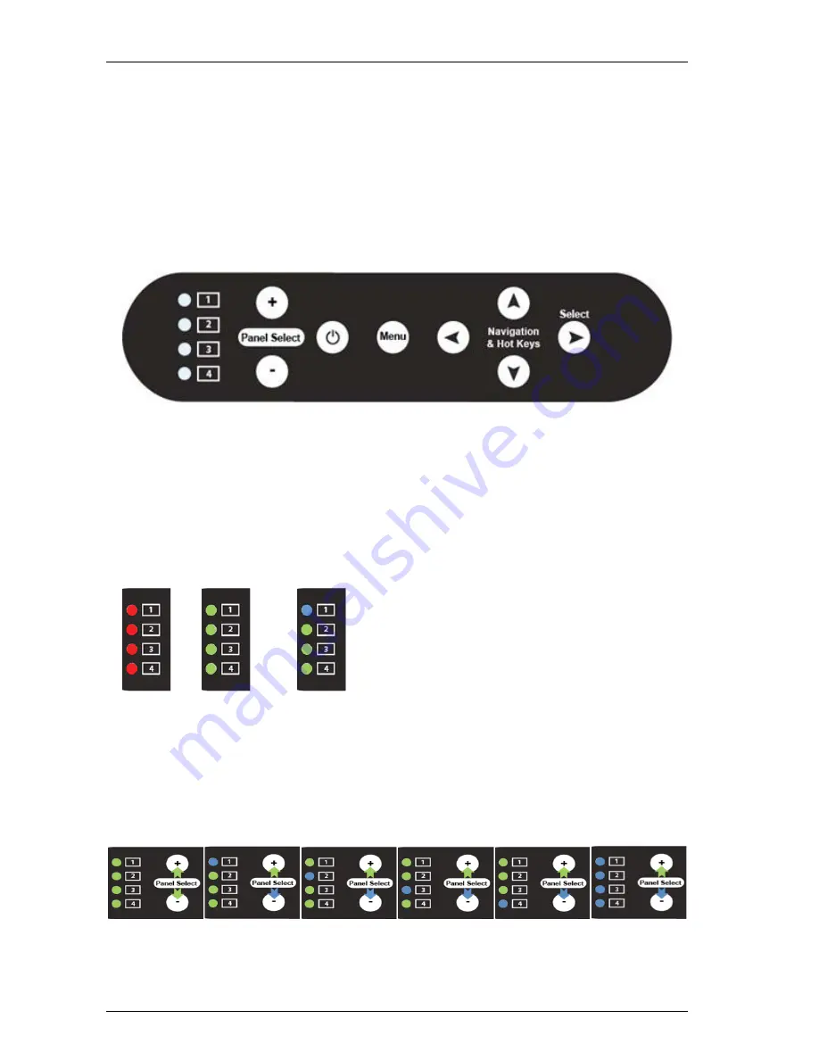
The OSD button board located on display screen one (1), i.e. the center display screen, is illustrated below. 


The basic functions of the OSD button board are: 

•  

Power Button – Turns the TMM4500 on and off 

•  

Menu – Activates the OSD set-up menu 

•  

Navigation & Hot Keys, Up Arrow – Brightness 

•  

Navigation & Hot Keys, Down Arrow – Auto-Calibrate (VGA Only) 

•  

Navigation & Hot Keys, Left Arrow – Contrast 

•  

Navigation & Hot Keys, Right Arrow – Activates Volum3 

OSD


I

NDICATOR 

L

IGHT 

D

EFINITIONS 


The OSD button board has a bank of four (4) LEDs that indicate LCD display status.  


Here are the definitions of the OSD indicator lights:  

•  

Red  – Power is applied to an individual display screen, but no active video source is detected. 

•  

Green – Power is applied to an individual display screen, and an active video source is detected. 

•  

Blue – In the example above, display screen 1 is selected or “in focus”.  

•  

Focus Options – Display screen selection is accomplished by using the Panel  or - buttons 
shown below 

Reset / No Focus     Panel 1 Focus      Panel 2 Focus      Panel 3 Focus      Panel 4 Focus     All Panel Focus  


NOTE: The unified button board supports up to four displays.  TMM4500 configurations with fewer than 
four displays will have LEDs that are not populated. 


RED            GREEN        BLUE- Display 1 


No Video      Good Video      Shows Current 
  Signal             Signal                   Status 


5-1 


Trenton Systems, Inc. 

Summary of Contents for TMM4500

Page 1: ...TMM4500 4U 4 PANEL RACKMOUNT LCD MONITOR No TMM4500 xxx Revision A REFERENCE GUIDE Publication No 8404500 04044...

Page 2: ...r than Trenton or if failure is caused by accident acts of God or other causes beyond the control of Trenton Trenton reserves the right to make changes or improvements in any product without incurring...

Page 3: ...tem variables and application requirements associated with any particular installation Trenton Systems cannot assume responsibility or liability for actual system use based on the examples and diagram...

Page 4: ...RE YOU BEGIN 3 1 RACK MOUNTING 3 1 RACKMOUNT INSTRUCTIONS 3 1 CHAPTER 4 TMM4500 OPERATION 4 1 CONNECTING THE TMM4500 DISPLAYS 4 1 BACK PANEL LAYOUT AND CONNECTING TMM4500 POWER 4 1 DEPLOYING THE TMM45...

Page 5: ...TY INSTRUCTIONS Before handling the product read the following instructions and safety guidelines to prevent damage to the product and to ensure your own personal safety Refer to the Advisories sectio...

Page 6: ...g away from heat sources and sharp metal edges to avoid damage Keep product away from direct sunlight and heat sources Hot air may cause damage to the cabinet and other parts Install the product in a...

Page 7: ...rvice personnel in the event that Liquid is spilled in to the product or the product is exposed to rain or water The product does not operate properly when the operating instructions are followed The...

Page 8: ...upport for digital picture in picture Standard video inputs include VGA DVI CVS 2x YPbPr and HDMI Optional video input interfaces include Dual or single channel 3G HD SD SDI POWER 12VDC operation via...

Page 9: ...Sets of heavy duty steel solid bearing friction slides E Cage Style Cable Guides To protect and secure cabling for continuous use F Electronics Back Large area for easy connections and access to elect...

Page 10: ...TMM4500 Reference Guide Chapter2 MechanicalOverview TMM4500 LAYOUT DIMENSIONS AND OPTIONAL CONFIGURATIONS 2 1 Trenton Systems Inc...

Page 11: ...mputer are designed to secure the TRC4012 to the rack cabinet s front mounting rails RACKMOUNT INSTRUCTIONS A Determine the mounting location within the rack and mark the mounting holes in the front a...

Page 12: ...0 32 Panhead screws F With the remaining 10 32 screws secure the unit into the Rack Frame Removing the 2x 10 32 screws you were using as stops in the TIP and install them into the remaining hold of th...

Page 13: ...M4500 product configuration Use the appropriate video interface cable to connect each video input connector to the corresponding video output source BACK PANEL LAYOUT AND CONNECTING TMM4500 POWER Illu...

Page 14: ...ut the display assembly and rotate and rotate the display assembly to the stable deployment position STOWED POSITION 1 Unscrew the four thumb screws located on the unit s front face FULL EXTENSION 2 P...

Page 15: ...e component rack 2 Quarter Turn Latches Receptacles These quarter turn fasteners are used to secure the front face to the display drawer 3 Display Module Lock Down Latches The lockdown latches are use...

Page 16: ...tness Navigation Hot Keys Down Arrow Auto Calibrate VGA Only Navigation Hot Keys Left Arrow Contrast Navigation Hot Keys Right Arrow Activates Volum3 OSD INDICATOR LIGHT DEFINITIONS The OSD button boa...

Page 17: ...rical outlet Check that the monitor s power cable is connected properly and securely to an electrical outlet Check that the panel is in a raised position for the power switch to automatically activate...

Page 18: ...he display settings Horizontal Frequency 30kHz 61kHz Vertical Frequency 50kHz 75kHz Maximum Refresh Rate 1280 x 1024 75Hz Image is not centered on a display screen Adjust the screen s horizontal and v...

Page 19: ...Viewing Angle 89 Left of vertical center and 89 Right of vertical 178 total 89 Up over horizontal center and 89 Down from horizontal center 178 total Color Depth 16 7M Contrast Ratio 1000 1 Response...

Reviews: