


TMM4500 Reference Guide
D
EPLOYING
T
HE
TMM4500
–
B
ASIC
D
ISPLAY
D
RAWER
O
PERATION
CAUTION
Ensure that the TMM4500 is securely mounted in the component
rack before opening and extending the display drawer.
The display head of the TMM4500 contains the majority of the unit weight. Failure to secure the unit before
sliding open the display drawer will cause the unit to tip forward and may result in system damage or injury.
For pre-installation, testing situations the back of the unit should be secured to a stable surface or countered-
weighted to prevent the unit from tipping forward.
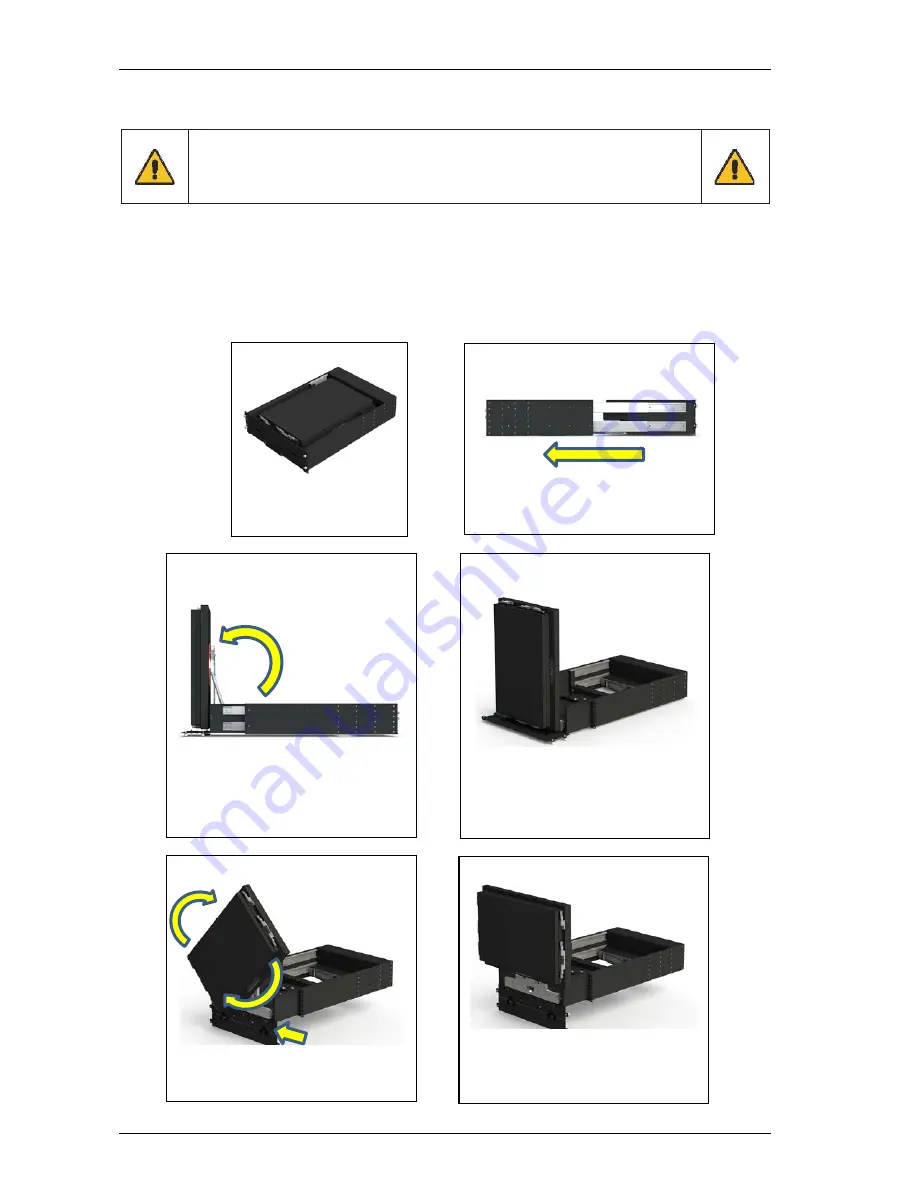
Follow the steps below to open the TMM4500 display drawer, slide out the display assembly and rotate and
rotate the display assembly to the stable-deployment position.
STOWED POSITION
1.
Unscrew the four
thumb screws located
on the unit’s front face
FULL EXTENSION
2.
Pull drawer out
3.
Unlock the two ¼ turn latches
4.
Fold front face down 180 degrees
FULL EXTENSION - UP
6.
Release any display securing
latches that may be engaged
7.
Grab back of display head
8.
Lift display head up 90°
STABLE – VERTICAL
5.
Push the display head into the
stable up position just far enough
the clear the component rack,
transit case or pre-installation test
station
ROTATION MANEUVER
10.
Ensure front face is hanging
straight down at 180° as shown
11.
Rotate display head 90°
STABLE - HORIZONTAL
9.
STOP!
Before opening the display
head, the front face must be setup
to enable the display head module
stop. See the next step.
Trenton Systems, Inc.
4-2


