MBS1000 Installation Guide
Trenton Systems, Inc.
ii
Before You Begin
I
NTRODUCTION
It is important to be aware of the information listed below before installing your Trenton modular blade
server. System performance may be affected by incorrect usage of these features.
E
XTERNAL
P
OWER
S
OURCE
–
R
EDUNDANT
900W
AC/DC
P
OWER
S
UPPLY
V
ERSION
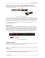
Incoming AC power must be supplied to both of the power supply receptacles located at the rear of the
chassis.
These dual AC power connections ensure that the active system power supply; as well as the
stand-by/fail-over supply, is each connected to a power source with a solid earth ground, and each supply
must have an incoming power source of: 100-127/200-240VAC, 10A/5A at 50 to 60Hz.
This power supply option may also be connected to incoming DC power sources capable of delivering 200-
250VDC at 5.5A to each power supply receptacle. A breaker rated at 125% of the marked DC input rating
must be provided as part of building installation.
Under each incoming power connection scenario, this power supply option de12VDC and +12VDC
AUX to the system at 73.8A and 2.5A respectively. Total output power must not exceed 900W.
E
XTERNAL
P
OWER
S
OURCE
–
R
EDUNDANT
750W
-48VDC
P
OWER
S
UPPLY
V
ERSION
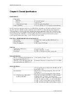
Incoming -48DC power must be supplied to each three-position connector located at the rear of the chassis
on the two DC power supply assemblies.
These dual DC power connections ensure that the active system
power supply; as well as the stand-by/fail-over supply, is each connected to a power source with a solid
earth ground. Each supply must have an incoming power source of:-48 to -60VDC, 20.4A DC typical, and
the maximum input current must not exceed 23A. The -48VDC power supply option de12VDC and
+12VDC AUX to the system at 61.5A and 2.5A respectively. Total output power must not exceed 750W.
A breaker rated at 125% of the marked DC input rating must be provided as part of building installation.
The power supply must only be used with Trenton power cable P/N 193500001938-00. Contact Trenton for
this part.
C
HASSIS
A
IRFLOW
When installing the chassis, ensure that a minimum free air space is available around the system. The
installation should have a minimum of 4-6 inches (101-152mm) behind the chassis and 7-8 inches
(178-203mm) in front of the chassis. Any front cabinet doors or access aisles must accommodate a
MBS1000 front chassis clearance of at least 7.0” (178mm) in order to provide proper clearance for the fan
FRU replacement. Ideally, a chassis clearance of 0.5-1.5 inches (13-38mm) above the system is desirable.
C
HASSIS
R
ACK
M
OUNTING
The MBS1000 system can be installed in a rackmount cabinet that conforms to EIA standards for server
equipment with 19-inch wide panels. The cabinet must be tall enough to accommodate the server’s height
and deep enough to accommodate the system’s depth, while providing the proper clearances for air flow
and cabling. A cabinet with a standard depth of 31.5 inches (800mm) will provide the suggested minimum
rear chassis clearances needed for an installation.


