MBS1000 Installation Guide
Trenton Systems, Inc.
3-2
S
LIDE
R
AIL
I
NSTALLATION
Trenton offers a slide rail kit to help with the installation of a 1U Trenton Systems’ MBS1000 modular
blade server. Here are the installation instructions for the Trenton 26” Slide Rail kit (part no.
198500001127-00).
1.
Remove slide rails from the box along with the rail frames, optional rack frame mounting brackets
and the mounting hardware. The Trenton 26” Slide Rail kit includes the following items.
2, 26”, three-section slide rails
2, chassis rack slide brackets
2, 1U chassis mounting ears
2, 1U component rack mounting ears
1, mounting hardware bag 10, #8-32 thumb screws
2.
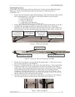
Remove the two chassis rack slide brackets from the slide rail kit and attach each one to the sides
of the MBS1000 by aligning the bracket’s mounting holes with the server’s slide bracket
mounting posts. When all three are aligned, slide the bracket toward the rear of the chassis until
you hear an audible click indicating that the bracket has locked into place. Refer to Figures 1 & 2.
3.
Remove the 1U mounting ear screws and discard the spacing washers. Use the screws to attach
the 1U chassis mounting ears to the MBS1000.
4.
Standard 19” instrument racks have a wide variety of mounting hole types. Some mounting holes
are threaded, but most of not, some mounting holes are located on side flanges rather than the
front and back of the rack supports and finally some holes are round while others are rectangular.
Our installation photos and the following steps assume that your 19” instrument rack has
rectangular, non-threaded mounting holes (i.e. window holes) for the slide rail frames. If your
rack has other mounting-hole types or placements, then you may need to consult with your rack
supplier to obtain the correct slide rail mounting hardware.
5.
Using five #8-32 thumb screw, attach a three-section slide rail to the left side of the component
rack with the three-hole bracket toward the rear of the rack as shown in Figure 3A.
Chassis rack slide bracket
(2)
Rack slide bracket
mounting post
(3 per side)
1U mounting ears
(2)
Figure 1 – Chassis rack slide detail
1U mounting ear
attachment screws
(2 per side)
Figure 2 – Chassis rack slide and 1U mounting ear installed
Slide bracket lock
1U mounting ear installed
Right-side disconnect lever
Figure 3 – Slide rail installation
3A 3B


