

OPERATION
Foreword
Thank you for your purchase of the TRELAWNY
TFP200 Floor Planer.
This manual contains the necessary maintenance
information for you to ensure proper operation and
care for this machine.
See also the manual that is supplied by the
engine manufacturer.
It is essential for you to read through these
manuals thoroughly.
In the unlikely event that you experience problems
with your TFP200, please do not hesitate to contact
your local Trelawny dealer or agent. We always
welcome feedback and comments from our valued
customers.
General Information
Before operating, performing maintenance or
repairing the TFP200 Floor Planer this manual must
be read and understood by the operator, if in any
doubt, ask your supervisor before using this
equipment.
Local safety regulations must be followed at all
times. Failure to follow these instructions could result
in damage to the TFP200 and/or personal injury.
Trelawny SPT Limited disclaims all responsibility for
damage to persons or objects arising as a
consequence of incorrect handling of the machine,
failure to inspect the machine for damage or other
faults that may influence the operation prior to
starting work, or failure to follow the safety
regulations listed or applicable to the job site.
This machine is primarily designed for the removal of
paint, heavy rust, scale and for the removal of
laitance from concrete from floor areas. It can be
used both indoors and out. Electric and compressed
air models are more suitable for indoor use because
of the toxic gases that are produced by petrol
engines.
Air Supply
(Air Motor Versions)
The compressed air must be free from water and
dirt. The installation of a filter/regulator/lubricator air
preparation set (with moisture trap) adjacent to the
tool is
strongly recommended
.
Always clear the air hose before connecting to the
tool. Ensure that no moisture (condensation) is
present in the air hose.
Ensure that a minimum 19mm (3/4”) bore air hose is
used and that all couplings are secure, leak free and
in good condition.
Limit the length of air hose to 30M (100ft). Where
extra length is necessary, for each additional 15M
(50ft) of air hose used, the pressure drop is
approximately 0.21bar (3psi).
For safe and efficient operation the correct
operating pressure is 6.2bar (90 psi).
Do not let the operating pressure fall below 5.5bar
(80p.s.i.) or rise above 6.9bar (100 psi).
Preferably, the compressor should be able to supply
a minimum of 95 L/s (200 cfm) free air.
In particularly cold weather it is recommended that a
proprietary anti-freeze lubricating oil is used.
Safety
WEAR
SAFETY
BOOTS,
FACE
MASK,
SHATTERPROOF
GLASSES,
HELMET,
GLOVES and any other personal protective
equipment required for the working conditions.
Avoid loose clothing; this may become trapped
in moving parts and cause serious injury.
TO AVOID NUISANCE DUST, connect an industrial
vacuum cleaner (minimum 3000watts or
equivalent) to the 50mm (2”) vacuum port
situated at the rear of the machine.
ENSURE THAT THE WORK PLACE IS WELL
VENTILATED.
Avoid
operating
engine-
powered machines in an enclosed area, since
engine exhaust gases are poisonous.
BE VERY CAREFUL WITH HOT COMPONENTS.
Exhausts and other parts of the engine are hot
during operation and can remain hot for some
time after shutdown.
DO NOT
REFUEL THE ENGINE WHILE THE
ENGINE IS HOT OR RUNNING, there is a
very real danger from explosion – always
refuel when the engine is cold, and in the open
air.
During transportation fasten fuel cap tightly and
close fuel cock.
DO NOT
carry out any work on this machine without
disconnecting it from its air or electrical power
supply.
CAUTION THIS MACHINE IS HEAVY. It weighs
around (Wt 73 kg (161 lbs)) dependent on
power unit. Do not lift this machine manually.
IMPORTANT:
When fitted with a petrol engine, AVOID TIPPING
THE TFP200 BACKWARDS, especially when hot;
the engine oil can run past the piston and into the
combustion chamber causing the piston to “hydraulic
lock” when next attempting to start the engine. Never
attempt to forcibly turn the engine over if this has
taken place, severe damage to the engine can be
caused, resulting in a costly major strip down and
possible injury to the operator.
To remove any oil from the cylinder, first remove the
spark plug and place a lint free cloth over the
plughole to capture the jettisoned oil. Turn the
engine over with the ignition switch and fuel cock in
the off position and expel as much of the oil as
possible. Clean the spark plug to remove oil from the
electrodes and replace. The plug may have to be
removed and cleaned several times before the
engine will start. Upon starting, the engine may
produce smoke for a while from the exhaust, but this
should soon clear.
Finally stop the engine and recheck the engine oil
level. (Ensure that the engine is level prior to
carrying out this check). If the engine oil level is low,
refill with the recommended motor oil - see engine
manufacturers operating instructions.
Risk of Hand-arm
Vibration injury
These tools may cause Hand-arm Vibration
Syndrome injury if their use is not adequately
managed.
We advise you to carry out a risk assessment and to
implement measures such as; limiting exposure time
[i.e. actual trigger time, not total time at work], job
rotation, ensuring the tools are used correctly,
ensuring the tools are maintained according to our
recommendations, and ensuring that the operators
wear personal protective equipment [PPE]
particularly gloves and clothing to keep them warm
and dry.
Employers should consider setting up a programme
of health surveillance to establish a benchmark for
each operator and to detect early symptoms of
vibration injury.
We are not aware of any PPE that provides
protection against vibration injury by attenuating
vibration emissions.
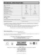
See ‘Specifications’ section for vibration
emission data.
Further advice is available from our Technical
Department.
We strongly advise you to visit the Health & Safety
Executive website http://www.hse.gov.uk/vibration
This site provides excellent advice and information
on HAV and currently, includes a Hand-arm
Vibration Exposure Calculator that is easy to use to
work out the daily vibration exposure for each of your
operators.
Cutter types &
Applications
T.C.T
Hardened steel cutter with tungsten carbide inserts.
For all general cleaning applications, including
concrete texturing, Scabbling, the grooving of
concrete, removal of embedded roof chippings,
brittle coatings from steel work. Use TCT Cutters on
heavy applications, for longer life and higher output.
Produces “tramlines” on concrete and small
indentations on steelwork.
STAR
Heat-treated steel cutters used for the aggressive
removal of paint and coatings from floor areas, but
with a shorter life span than Beam Cutters. Can be
used for the general removal of dirt and ice deposits
and to produce a texture on concrete surfaces.
Produces roughened surface on concrete and light
marking on steelwork.
BEAM
Heat-treated steel cutters used for the removal of
paint and coatings from floor areas, but with a
shorter life span that TCT Cutters, not as aggressive
as Star Cutters. Can be used for the general removal
of dirt and ice deposits.
Produces a fine texture on
concrete surfaces and slight marking on steelwork.
MILLING
Flat tungsten carbide cutters for the removal of
thermo-plastic road and runway markings. Very
efficient and cost effective with none of the problems
associated with burning off. These can also be used
for the removal of bituminous and rubber deposits.
Very effective for the removal of two part epoxy floor
paint, may require finishing with beam cutters or the
Trelawny floor grinder to achieve the required finish.
Note: Care must be taken with milling cutters to
ensure that the Drum and its Cutters are is fitted the
correct way round, the tungsten carbide tips must
face towards the vacuum port at the bottom as the
drum rotates, otherwise the tips will be damaged in
use.
Produces a “strip” on concrete and tarmac, is
not recommended on steelwork unless for “braking
up” coatings.
NB: Increasing or decreasing the number of spacers
used can alter the performance and finish
characteristics of each cutter type. Ensure that the
same type and quantity of spacers and cutters are
fitted to the opposite cutter shaft to maintain the
drums balance. An out of balance drum can be very
dangerous and will also dramatically increase the
vibration emissions.
Changing Cutter Drums
Turn off and stop the machine, making sure the
cutter drum has come to a complete standstill.
If electric or air powered, disconnect the
machine from the power source.
Adjust the height adjustment hand wheel so that the
cutters are clear of the ground.
Remove the four Side Plate retaining bolts and
remove the Side Plate. If the Side Plate is stuck in
it‟s opening or on the dowel pins, use two of the Side
Plate retaining bolts inserted into the threaded holes
on each side of the Side Plate. Screw in both of
these bolts equally until the Side Plate is free.
Summary of Contents for TFP200
Page 1: ...TFP200 FLOOR PLANER OPERATION MAINTENANCE ...
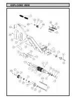
Page 6: ...EXPLODED VIEW ...
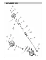
Page 7: ...EXPLODED VIEW ...