MAINTENANCE
With the Plate removed the Cutter Drum will simply
slide off the Drive Shaft. The fitting of the drum is
basically the reverse of the removal procedure.
When changing cutter drums always check that the
flail shafts are not excessively worn with pronounced
grooves, also that the centres of the cutters and
spacers and check that the drum flail shaft location
holes are not elongated. The screws which hold the
drum end plates in position must be tight and in good
condition.
Note:
In general use it is expected that normally two
sets of flail shafts will be used to one set of TCT
cutters. While changing the drum the condition of the
drive shaft, the drum‟s hexagon drive, the drive shaft
bearings and side plate bearing should be checked.
If any roughness, side play or leakage of grease is
detected then new bearings should be fitted. Lightly
oiling the drive shaft will prevent a build up of rust,
which could cause difficulty when changing the drum
later. While the Drum is removed, check that the
vacuum port is free from blockages and that the
wear strip, which also retains the dust skirt are both
in good condition. Replace any damaged, worn or
suspect parts. Ensure that all the bolts are tight at all
times, recheck at regular intervals.
Cutter Replacement &
Configurations
Replacing cutters/spacers/flail shafts
Remove Drum; see
Changing Cutter Drums
.
Unscrew the four countersunk screws and locknuts
from either end of the Cutter Drum.
Using a suitable drift, push out each of the flail
shafts. Check each of the flail shafts for wear and
replace as required. Check also the Drum, Cutters
and Spacers for elongation and hole enlargement,
replace as necessary.
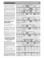
See the table below for the examples of the
sequence of spacers /cutters for each style of drum.
Before loading any cutters, establish which is
“Position 1”. (See next)
Position the two shorter rows to the left and at the
top as you look at the drum; identify the short row on
the left furthest away from you (at the “back” of the
drum), this is “Position 1”
For ease of assembly, mark the end of the drum to
help identify each flail shaft, rotate the drum away
from you marking each position in order. 1,2,3,4.
The drum’s web plate thickness and positions
can vary slightly; because of this, the quantity of
cutter and/or spacers may need to be adjusted,
ensure that the same amount of cutters and
spacers are fitted to opposite shaft to keep the
drum balanced. These examples are for
illustrative purposes only.
Method as per Single Web Drum;
Insert a flail shaft into the drum from the left side, in
position 1, so that its end is in the middle of the short
row, start to load with a single spacer first, fit the 9
cutters alternating with a spacer until the last cutter,
pushing the fail shaft further through as the shaft fills,
in this case end the short row with 1 single spacer.
Continue with the long row on the same shaft, but no
spacer is fitted before or after the last cutter (See
example below)
Rotate the drum away from you to complete shaft
2,3 and 4.
Finally secure the end plates with the four
countersunk screws and four new locknuts.
Example
for Position 1: - (Short Row) 1 x spacer,
followed by 9 x cutters and with a single spacer after
each cutter, but ending with a single spacer after the
last cutter. Continue with the long row, no spacer,
followed with 12 x cutters with a single spacer after
each cutter, ending with no spacer after the last
cutter.
Milling Cutter Single Web Drum (Economy load)
Example for Position 1: - (Short Row) 4 x spacers, followed by 1 x cutter, then 6 x spacers, followed by 1 x cutter, ending with 5 x
spacers, continue with the long row, 4 x spacers followed with 1 x cutter, then 8 x spacers followed by 1 x cutter ending with 9 x
spacers.
TCT CUTTERS FITTED TO SINGLE WEB DRUM
Position
Short Row
Left
Centre
Web
Long Row
1
1sp-9c-1sp
0sp-12c-0sp
2
2sp-9c-0sp
1sp-11c-2sp
Long Row
Right
Centre
Web
Short Row
3
0sp-12c-0sp
1sp-9c-1sp
4
2sp-11c-1sp
0sp-9c-2sp
TCT CUTTERS FITTED TO DOUBLE WEB DRUM
Position
Left Row
Left
Web
Middle Row
Right
Web
Long Right Row
1
0sp-6c-0sp
0sp-6c-0sp
0sp-8c-1sp
2
2sp-5c-1sp
1sp-5c-2sp
1sp-8c-0sp
Long Left Row
Left
Web
Middle Row
Right
Web
Right Row
3
1sp-8c-0sp
0sp-6c-0sp
0sp-6c-0sp
4
0sp-8c-1sp
2sp-5c-1sp
1sp-5c-2sp
MILLING CUTTERS FITTED TO SINGLE WEB DRUM (Standard load)
Position
Short Row
Left
Centre
Web
Long Row
1
1sp-1c-1sp-1c-2sp-1c-1sp
1sp-1c-3sp-1c-3sp-1c-6sp
2
1sp-1c-2sp-1c-1sp-1c-1sp
6sp-1c-3sp-1c-3sp-1c-1sp
Long Row
Right
Centre
Web
Short Row
3
6sp-1c-3sp-1c-3sp-1c-1sp
1sp-1c-2sp-1c-1sp-1c-1sp
4
1sp-1c-3sp-1c-3sp-1c-6sp
1sp-1c-1sp-1c-2sp-1c-1sp
Milling Cutter Single Web Drum (Full load)
Example for Position 1: - (Short Row) 3 x full milling cutters, followed by 1 x ½ size milling cutter, continue with the long row, 4 x full
milling cutters, followed by 1 x ½ size milling cutter.
MILLING CUTTERS FITTED TO SINGLE WEB DRUM (Full load)
Position
Short Row
Left
Centre
Web
Long Row
1
0sp-3c-½c-0sp
0sp-4c-½c-0sp
2
0sp-½c-3c-0sp
0sp-½c-4c-0sp
Long Row
Right
Centre
Web
Short Row
3
0sp-½c-c4-0sp
0sp-½c-3c-0sp
4
0sp-4c-½c-0sp
0sp-3c-½c-0sp
Milling Cutter Double Web Drum
Example for Position 1: - (Left Row) 6 x spacers, followed by 1 x full cutter, ending with 6 x spacers, continue with the (Middle
Row), no x spacer, followed by 1 x full cutter, then 3 x spacers, then 1 x full cutter ending with no spacers, continue with the (Long
Right Row), 3 x spacers, followed by 1 x full cutter, then 1 x half cutter, followed by 1 x full cutter, finishing with no spacer.
MILLING CUTTERS FITTED TO DOUBLE WEB DRUM
Position
Left Row
Left
Web
Middle Row
Right
Web
Long Right Row
1
6sp-1c-6sp
0sp-1c-3sp-1c-0sp
3sp-1c-½c-1c-0sp
2
0sp-1c-3sp-1c-0sp
1sp-1c-1sp-1c-1sp
0sp-1c-½c-1c-3sp
Long Left Row
Left
Web
Middle Row
Right
Web
Right Row
3
0sp-1c-½c-1c-3sp
0sp-1c-3sp-1c-0sp
6sp-1c-6sp
4
3sp-1c-½c-1c-0sp
1sp-1c-1sp-1c-1sp
0sp-1c-3sp-1c-0sp
The drum’s web plate positions may vary slightly; because of this the quantity of cutter and spacers may need to be
adjusted, these examples are for illustrative purposes only.
CUTTERS & SPACER QUANTITIES FITTED TO SINGLE WEB DRUM
CUTTER TYPE
PART No
CUTTERS
SPACERS
TCT
320.5500
82
88
Beam
320.5120
272
0
Star
320.3658
208
0
Milling (Economy)
320.5600
16
144
Milling (Standard)
320.5600
24
72
Milling (Full load)
320.5600 / 320.5650
28 full / 8 half
0
Spacer
320.4140
CUTTERS & SPACER QUANTITIES FITTED TO DOUBLE WEB DRUM
CUTTER TYPE
PART No
CUTTERS
SPACERS
TCT
320.5500
76
80
Beam
320.5120
268
0
Star
320.3658
204
0
Milling (Full load)
320.5600
22 full / 4 half
54
WIRE BRUSH QUANTITIES FITTED TO BRUSH HOLDER
Wire Brush
Spacers
Crimped Wire Brush
16
16
Twisted Wire Brush
23
23
MILLING CUTTERS FITTED TO SINGLE WEB DRUM (Economy load)
Position
Short Row
Left
Centre
Web
Long Row
1
4sp-1c-6sp-1c-5sp
4sp-1c-8sp-1c-9sp
2
1c-15sp-1c
1c-6sp-1c-15sp
Long Row
Right
Centre
Web
Short Row
3
9sp-1c-8sp-1c-4sp
5sp-1c-6sp-1c-4sp
4
15sp-1c-6sp-1c
1c-15sp-1c
Milling Cutter Single Web Drum (Standard load)
Example for Position 1: - (Short Row) 1 x spacers, followed by 1 x cutter, then 1 x spacers, 1 x cutter, 2 x spacers, 1 x cutter,
ending with 1 x spacer. Continue with the long row, 1 x spacers, 1 x cutter, then 3 x spacers, 1 x cutter, 3 x spacers, 1 x cutter,
ending with 6 x spacers.
Summary of Contents for TFP200
Page 1: ...TFP200 FLOOR PLANER OPERATION MAINTENANCE ...
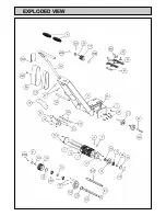
Page 6: ...EXPLODED VIEW ...
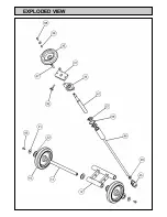
Page 7: ...EXPLODED VIEW ...


