


14
STEP
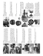
36:
Reinstall
the
carburetor
with
a
new
O-ring,
header,
a
NEW
glow
plug,
and
engine
mount.
Use
a
new
header
gasket
when
re-installing
the
header
on
the
engine.
Reinstall
the
engine
in
the
truck
in
the
reverse
order
of
removal.
Don’t
forget
to
reconnect
the
yellow
grounding
wire
to
the
engine
mount.
The
rebuilt
engine
must
now
be
broken
in.
STEP
31:
Reinstall
the
backplate
and
a
new
backplate
gasket
with
the
3x8mm
cap-head
machine
screws.
Tighten
the
screws
in
small
increments,
in
a
criss-cross
pattern
until
all
the
screws
are
tight.
STEP
32:
Install
the
appropriate
size
ball
bearing
into
one
side
of
the
clutch
bell
gear.
The
Nitro
Stampede
comes
stock
with
an
18-tooth
clutch
bell
gear
which
requires
5x11mm
ball
bearings.
STEP
33:
Turn
the
gear
over
and
install
the
other
ball
bearing.
STEP
34:
Install
the
split-beveled
cone
onto
the
crankshaft.
Next,
install
the
flywheel.
Install
the
clutch
adapter
nut
with
a
10mm
deep
socket.
Grip
the
flywheel
with
pliers
while
tightening
the
adapter
nut.
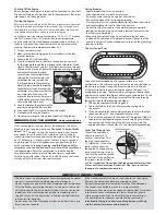
STEP
35:
Install
the
clutch
shoes
exactly
as
shown
in
the
drawing
(leading
edge
engagement).
Next,
install
a
5x8mm
Teflon
®
washer
followed
by
the
clutch
bell
gear
(with
bearings
installed).
Install
the
remaining
5x8mm
Teflon
®
washer
followed
by
the
E-clip
(see
step
14).
STEP
25:
To
assemble
the
connecting
rod
and
piston,
place
a
drop
of
castor
oil
in
the
top
end
of
the
connecting
rod.
Insert
the
wrist
pin
through
the
piston
and
the
top
of
the
connecting
rod.
Secure
the
wrist
pin
with
the
G-clip.
Make
sure
the
G-clip
fits
securely
into
the
groove
machined
in
the
piston.
Be
careful
not
to
scratch
the
sides
of
the
piston.
STEP
26:
Reinstall
the
crankshaft
into
the
engine
and
make
sure
that
it
spins
freely.
Insert
the
connecting
rod
and
piston
assembly
through
the
top
of
the
crankcase.
The
G-clip
should
face
the
carburetor.
Put
a
drop
of
castor
or
after-
run
oil
in
the
bottom
end
of
the
connecting
rod.
Use
your
fingers
to
gently
push
the
end
of
the
connecting
rod
over
the
crankshaft
journal.
STEP
27:
Place
another
drop
of
oil
on
the
connecting
rod
bushing.
Rotate
the
crankshaft
several
times
to
distribute
the
oil.
STEP
28:
Insert
the
sleeve
into
the
top
of
the
crankcase.
Rotate
the
sleeve
so
that
the
notch
in
the
sleeve
will
line
up
with
the
pin
in
the
crankcase.
Holding
the
engine
upside
down
will
make
it
easier
for
the
sleeve
to
go
over
the
piston.
STEP
29:
Install
new
head
gaskets
on
the
head.
Use
one
thick
and
one
thin
gasket.
Reinstall
the
head
using
the
3x12mm
cap-head
machine
screws.
Tighten
the
screws
in
small
increments,
in
a
criss-cross
pattern,
until
all
the
screws
are
tight.
STEP
30:
Reinstall
the
starter
shaft.
Align
the
notch
in
the
starter
shaft
with
the
crankshaft
journal
pin
(arrow).


