background image

13

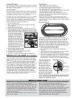
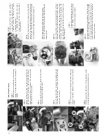
STEP 

15:

Remove 

the 

connecting 

rod 

and 

piston 

through 

the 

top 

of 

the 

crankcase.

STEP 

16:

To 

remove 

the 

connecting 

rod 

from 

the 

piston, 

use 

sharp-pointed 

tool 

to 

remove 

the 

small 

metal 

G-clip 

in 

the 

side 

of 

the 

piston. 

Do 

not 

re-use 

the 

old 

G-clip. 

When 

installing 

new 

connecting 

rod, 

use 

the 

supplied 

new 

G-clip.

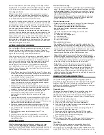
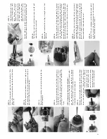
STEP 

21:


Remove 

the 

crankshaft 

by 

pulling 

it 

straight 

out 

of 

the


crankcase.

STEP 

22:

The 

bearings 

are 

press-fit 

into 

the 

crankcase. 

To 

remove 

them, 

the 

crankcase 

must 

be 

heated 

with 

heat 

gun 

or 

torch. 

The 

crankcase 

will 

expand 

with 

heat 

and 

release 

the 

bearings. 

To 

avoid 

the 

possibility 

of 

burns 

or 

other 

damage, 

do 

not 

attempt 

remove 

the 

bearings. 

Clean 

the 

bearings 

by 

flushing 

them 

with 

denatured 

alcohol 

and 

then 

place 

one 

or 

two 

drops 

of 

after-run 

oil 

on 

the 

races.

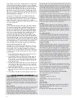
STEP 

23:

Before 

installing 

new 

connecting 

rod, 

you 

can 

increase 

connecting 

rod 

life 

by 

polishing 

the 

crankshaft 

journal. 

Use 

1200 

grit 

sandpaper 

to 

remove 

the 

surface 

scratches 

followed 

by 

liquid 

metal 

polish 

to 

buff 

the 

crankshaft 

journal 

to 

bright, 

smooth 

shine. 

Rinse 

thoroughly 

with 

denatured 

alcohol. 

Lube 

with 

after-run 

oil.

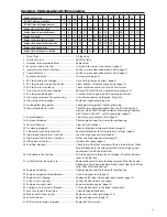
STEP 

24:

Use 

the 

1200 

grit 

sandpaper 

and 

the 

liquid 

metal 

polish 

on 

the 

wrist 

pin 

also. 

Rinse 

thoroughly 

with 

denatured 

alcohol 

and 

lube 

with 

after-run 

oil.

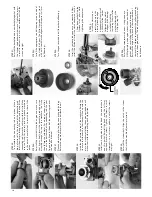
STEP 

13:

Pull 

the 

sleeve 

straight 

up 

and 

out 

of 

the 

crankcase. 

If 

the 

sleeve 

will 

not 

move, 

rotate 

the 

crankshaft 

until 

the 

sleeve 

pushes 

up.

STEP 

14:

Rotate 

the 

crankshaft 

to 

bottom 

dead 

center. 

Lightly 

 grab 

the 

connecting 

rod 

with 

pair 

of 

needlenose 

pliers 

and 

gently 

pull 

it 

off 

of 

the 

crankshaft 

journal.

STEP 

17: 

Removing 

the 

clutch 

and 

flywheel

It 

is 

not 

necessary 

to 

remove 

the 

clutch 

assembly 

unless 

you 

are 

se

rvicing 

th

clutch,


crankshaf

t, 

or 

engine


bearings. 

Use 

the 

tip 

of 

small 

screwdriver 

to 

remove 

the 

E-clip 

which 

holds 

the 

clutch 

bell 

gear. 

STEP 

18:

Remove 

the 

clutch 

bell 

gear 

and 

the 

clutch 

shoes. 

Note 

that 

there 

are 

two 

5x8mm 

Teflon

®

 washers, 

one 

on 

each 

side 

of 

the 

clutch 

bell 

gear. 

Check 

the 

clutch 

shoes 

for 

excessive 

wear 

or 

cracking


around 

the 

pin 

holes. 

If 

the 

clutch 

shoes 

are 

worn 

to 

the 

point 

that 

the 

clutch 

spring 

contacts 

the 

clutch 

bell, 

then 

the 

shoes 

must 

be 

replaced. 

STEP 

19:


Grip 

the 

flywheel 

with 

pair 

of 

pliers 

(locking 

pliers 

work 

best). 

Remove 

the 

clutch


adapter 

nut 

with 

10mm


deep 

socket. 

Hold 

the 

engine 

just 

above 

your 

workbench 

and 

tap 

the 

flywheel 

from


behind 

with 

non-marring 

hammer 

(plastic 

or 

wood). 

Several 

easy 

blows 

may 

be 

necessary 

to 

release 

the 

flywheel 

and 

split 

beveled 

cone.

STEP 

20:

The 

flywheel 

and 

the 

split-beveled 

cone 

should 

pull 

smoothly

 off 

of 

the 

crankshaft.

Summary of Contents for Nitro Stampede

Page 1: ...OPERATING INSTRUCTIONS COVERS MODEL 4109 KC0532 R01 Part 4199X Rev 090731...

Page 2: ...liable for any loss or damages whether direct indirect special incidental or consequential arising from the use misuse or abuse of this product and any chemical or accessory required to operate this...

Page 3: ...iation for nickel cadmium The original rechargeable hobby pack NiCad batteries have very high current handling high capacity and can last up to 1000 charging cycles Good charging procedures are requir...

Page 4: ...erent channels numbered 1 through 6 Each of the six channels is represented by a color Look at the crystal in the back of the transmitter to determine on which of the channels your truck is operating...

Page 5: ...fit on initial startup is desirable for those who want the best performing engine Make sure you are using a good quality battery pack that is fully charged new batteries usually require several charg...

Page 6: ...d with the engine break in 8 Do not rev your engine with no load wheels off the ground BREAKING IN THE ENGINE VERY IMPORTANT Once your engine is running it must be broken in The key to breaking in you...

Page 7: ...temperature 1 Turn the throttle trim on the transmitter so that the brakes are applied This ensures that the throttle barrel is resting against the idle adjustment screw 2 If necessary remove the air...

Page 8: ...life The ride height for Nitro Stampede can be adjusted by adding or removing the clip on spring pre load spacers Instead of adding spacers to increase stiffness use stiffer springs Adjust the ride he...

Page 9: ...e requires timely maintenance in order to stay in top running condition Neglecting the maintenance could allow dirt deposits and moisture to build up inside the engine leading to internal engine failu...

Page 10: ...uire periodic maintenance and are intended to be used in high performance applications over an extremely wide range of running conditions and situations no warranties are expressed or implied that cov...

Page 11: ...ixture is too lean Richen the high speed mixture page 7 24 Idle speed set too low Increase idle speed page 7 25 Fuel flow blocked Check that all fuel lines are clear with no pin hole leaks Check for d...

Page 12: ...he engine from the chassis Turn the engine so that the throttle linkage to the carburetor will come out STEP 9 Changing the piston and sleeve assembly Use a 5 16 inch nut driver to remove the glow plu...

Page 13: ...n also Rinse thoroughly with denatured alcohol and lube with after run oil STEP 13 Pull the sleeve straight up and out of the crankcase If the sleeve will not move rotate the crankshaft until the slee...

Page 14: ...see step 14 STEP 25 To assemble the connecting rod and piston place a drop of castor oil in the top end of the connecting rod Insert the wrist pin through the piston and the top of the connecting rod...

Page 15: ......

Reviews: