installed at the housing, ITEM 2, will pro-
vide an indication of the filter being
plugged; pressure reading over 4 psi.
maybe an indication that the filter needs
replacement. At higher discharge pres-
sures the discharged air quality will
decrease and the vacuum pump
absorbed power will increase.
To replace the oil demister filter, simply
disconnect the oil scavenger line,
remove the cover, ITEM 25, remove the
used filter element, apply a gasketing
material over the gasket faces of the
new filter and place the latter in the
housing, put in place the cover and the
scavenger line.
– 30 –
During operation it must be avoided to have sudden and frequent variations from
high to low vacuum. (e.g. suddenly opening the suction valve when the pump is
operating at pressures lower than 150 Torr). This would flood the pump creating
high power absorption that would put heavy stress on the motor and coupling.
Par ticular attention should be put on the quantity of the ser vice liquid flow. The
flow will depend upon the type of installation (see section 9), the pump size,
and/or the desired temperature rise. The flow of ser vice water at 15 °C, for stan-
dard pumps and normal operating conditions at various vacuum levels, is listed
on the specific pump cur ves and/or on table 3 of section 9.7. Usually the tem-
perature rise of ser vice water, when handling dr y air at 68 °F, is approximately 10
°F. When condensable (e.g.: vapours) are present in the gas stream the heat load
to be removed by the ser vice water will be higher, therefore the ser vice water tem-
perature rise will be higher. The ser vice liquid flow and its temperature will affect
the pump per formance. Generally the low ser vice liquid flow will decrease the
pump capacity, while a high ser vice liquid flow will increase the absorbed power
by flooding the pump (see section 17 for information and calculations). Hard ser v-
ice water will generate lime build-up inside the pump. The severity of the deposit
will var y with the water temperature. Lime or mineral deposits on the sur face of
the internal pump components will cause an increase of absorbed power, wear of
the components and eventually will seize the pump. It is recommended to moni-
tor the water hardness and, if too high, treat the water. If there are no alternatives,
there should be periodical flushing of the pump with a solution that will remove
the specific deposits, or the pump must be periodically disassembled, cleaned of
all incrustations and re-assembled. Systems with total ser vice liquid recover y
require periodical change of the ser vice liquid contained in the closed loop. The
heat exchanger must be kept well cleaned of all mineral deposits for an effective
thermodynamic heat exchange. During operation, a closed loop system will lose
some of the ser vice liquid, due to evaporation and/or saturation of the discharged
gases. It will be required to periodically make-up fresh liquid into the system. This
operation is not required for those systems that are fitted with a float type auto-
matic make-up valve ITEM 8. This valve requires water at a pressure of approxi-
mately 2 bar. Systems that handle condensable will experience a rise in the level
of the ser vice liquid in the separator. The excessive liquid will be over flowed
through the over flow valve or connection. If the specific gravity of the condensa-
ble is higher than that of the ser vice liquid, the condensable must be discharged
through the separator drain valve ITEM 11, preferably with system not running.
12.1 - “OIL SEALED (DynaSeal
TM
)” SYSTEMS
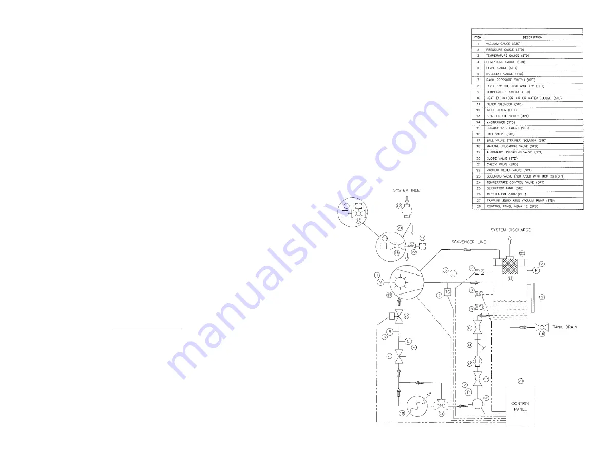
(For ITEM numbers refer to fig. 27 and it’s legend).
It is ver y impor tant to keep the ser vice oil temperature under control when the oil
temperature exceeds 90 °C there is the danger of seizing the pump and the gas-
keting may star t leaking.
Ever y 100 - 200 working hours it is suggested to check the oil level in the oil reser-
voir, make-up oil if necessar y and change the oil ever y 10,000 working hours
(depending upon the use and the application).
Those installations where the handled gases are contaminated with dust or sus-
pended solids that can alter the oil characteristics will require more frequent oil
check and changes.
Condensable vapors, if present during evacuation, can be flushed right through the
discharge of the separator (if they have low boiling point) or, when the system is
idle, can be drained by opening valves, ITEM 16. During operation, the oil demis-
ter filter will be impregnated with oil par ticles; the pressure gauge, ITEM 2,
– 29 –
TYPICAL BILL OF MATERIALS
Fig 27 (General Schematic Drawing)


