


4
S4TEF10xx-10x
17
24-Hour Technical Support: 1-800-260-1312 International: 00-1-952-941-7600
[email protected] -- Click the “Transition Now” link for a live Web chat.
Installation — Continued
Switch Set #1 - T1/E1 Options
5, 6, 7, 8 - Loop-Back Settings
The loop-back setting is used for installation and network debugging procedures. Each
of the T1/E1 ports can be individually set for loop-back mode:
• Switch 5 controls T1/E1 port 1 • Switch 6 controls T1/E1 port 2
• Switch 7 controls T1/E1 port 3 • Switch 8 controls T1/E1 port 4
When the loop-back switch for a particular T1/E1 port is enabled, the port loops the
signal from the receive port back to the transmit port.
Disable Loop-Back on T1/E1 port 1
Enable Loop-Back on T1/E1 port 1
up
5
down
Disable Loop-Back on T1/E1 port 2
Enable Loop Back on T1/E1 port 2
6
up
down
up
down
Disable Loop-Back on T1/E1 port 3
Enable Loop-Back on T1/E1 port 3
7
up
down
Disable Loop-Back on T1/E1 port 4
Enable Loop-Back on T1/E1 port 4
8
9 - Transmit AIS
Up - Enables the transmit AIS
(Alarm Indication
Signal)
on loss of the carrier signal. This function is
un-framed and applies to ALL channels, both copper
and fiber.
Down - Disables the transmit AIS function.
10 - RS-232 Port Mode
Up - Data port mode
(normal operation)
. Transmits
data to a desk top computer or other data collection
device
Down - Local
(auxiliary)
management mode. See
the SNMP section for the commands that are
supported via the RS-232 connector.
up
down
Enable
Disable
9
up
down
Data port mode
Local management mode
10
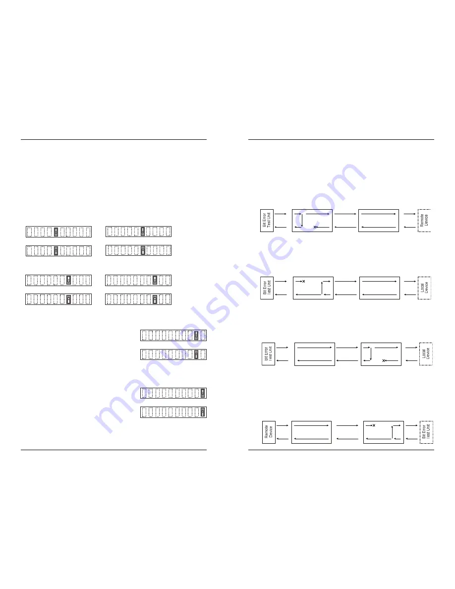
Troubleshooting — Continued
5.
Is data transfer failing on one of the T1/E1 ports?
YES
• Verify the local T1/E1 connection at the local Device by starting a local loop-
back at the local Device:
- HW mode: set the local Device to T1/E1 loop-back.
- SW mode: enter the local T1/E1 loop-back command at the local
Device.
• Use a bit error test unit to run a bit error test.
• Verify the remote T1/E1 connection at the local Device by starting a remote
loop-back at the local Device:
- SW mode: enter the remote T1/E1 loop-back command at the local
Device.
(HW mode is not available.)
• Use a bit error test unit to run a bit error test.
• Verify the remote T1/E1 connection at the remote Device by starting a remote
loop-back at the remote Device:
- SW mode: enter the remote T1/E1 loop-back command at the remote
Device.
(HW mode is not available.)
• Use a bit error test unit to run a bit error test.
• Verify the local T1/E1 connection at the remote Device by starting a local
loop-back at the remote Device:
- HW mode: set the remote Device to T1/E1 loop-back.
- SW mode: enter the local T1/E1 loop-back command at the remote
Device.
• Use a bit error test unit to run a bit error test.
r
e
p
p
o
C
r
e
b
i
F
r
e
p
p
o
C
Local
Device
Remote
Device
r
e
p
p
o
C
r
e
b
i
F
r
e
p
p
o
C
Remote
Device
Local
Device
r
e
p
p
o
C
r
e
b
i
F
r
e
p
p
o
C
Remote
Device
Local
Device
1
T
r
e
b
i
F
1
T
Local
Device
Remote
Device


