3-3
Chapter 3
AI1401 Reader Interface Capabilities
The AI1401 Reader is designed to interface with a variety of user
antennas and other equipment. This chapter outlines the AI1401 Reader
connectors and identifies their primary functions.
AI1401 Connectors
Because the AI1401 Reader combines the system reader and radio frequency (RF)
module into a single unit, the only connections that must be made to the system are the
antenna, actuator, and host computer connectors. These connectors are located at the
end of the AI1401 Reader. (See Figure 2-1 for the location of the connectors.) Figure
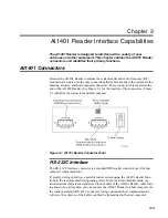
3-1 identifies the connectors and their purposes.
Figure 3-1 AI1401 Reader Connector Panel
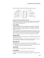
RS–232C Interface
The RS
–
232C interface connector is a standard DB9 socket connector used for host
computer communications.
Typically, during operation, a portable reader system using the AI1401 Reader func-
tions in the real-time disabled operating mode. In the real-time disabled mode, tag
identifications (ID) are read and stored in the buffer of the AI1401 Reader. After read-
ing and storing all tag data, you can connect the AI1401 Reader to a host computer via
the reader's standard RS
–
232C connector. Using customized host communications
software, the contents of the buffer can then be transmitted to the host computer.
Summary of Contents for AI1401
Page 2: ......
Page 5: ...Contents...
Page 6: ......
Page 9: ...1 Before You Begin...
Page 10: ......
Page 13: ...2 Overview...
Page 14: ......
Page 20: ...AI1401 Reader User Guide 2 8...
Page 21: ...3 AI1401 Reader Interface Capabilities...
Page 22: ......
Page 27: ...A Firmware Command Groups and Parameters...
Page 28: ......
Page 39: ...B AI1401 Character Conversion...
Page 40: ......
Page 42: ...AI1401 Reader User Guide B 4...


