


BAS-SVX065E-EN
17
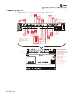
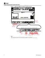
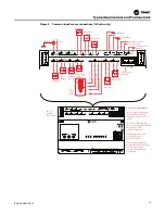
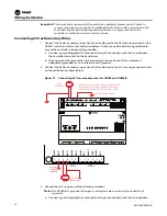
UC400 Wiring Diagrams
Figure 2. Common input/sensor connections (Trane EX units only)
VAC
24
XFRM
VAC
24
VAC
24
BI
1
BI
2
BI
3
LINK
IMC
+
24
VDC
BI
4
AO1
BI
5
AO2
UI
1
UI
2
AI
3
AI
2
AI
1
AI
4
AI
5
P
1
P
2
IMC
1
IMC
1
4
3
2
VAC
24
XFRM
VAC
24
VAC
24
BI
1
BI
2
BI
3
LINK
IMC
+
24
VDC
BI
4
AO1
BI
5
AO2
UI
1
UI
2
AI
3
AI
2
AI
1
AI
4
AI
5
P
1
P
2
C
NC
NO
BO3
C
NC
NO
BO2
C
NC
NO
BO1
RELAYS
ADDRESS
TRIAC SUPPLY
TRIACS
A
BO9
BO8
BO7
BO6
BO5
BO4
A
B
B
TX
RX
LINK IMC
SERVICE
SERVICE TOOL
CONNECT AC POWER TO THE TRAIC SUPPLY TO POWER THE TRIACS
BO1 BO2 BO3
BO4 BO5 BO6 BO7 BO8 BO9
1 2
3
4
56
7
8
9
IMC
1
IMC
1
3
4
56
7
1 2
3
4
56
7
8
9
8
9
Ground
24 Vac
Occupancy
(Open Occu)
Compressor
Lockout
Status
Defrost
Comm In
Comm Out
Supply F
an S
p
eed
S
p
ac
e
T
emp S
e
tp
oin
t
S
pac
e
T
emp
G
round
Pressure Inputs
*Condensate
Overflow
*Entering
Water Temp
*Relative
Humidity
Sensor
Fan
Status
ECM Fan
Motor
Space
Temp
Sensor
Two-Tier
Terminal
Connections
Leaving
Water Temp
Sensor
Disc harge
Air Temp
Zone Sensor Service
Tool Connection
Auxiliary 24 Vdc
Output
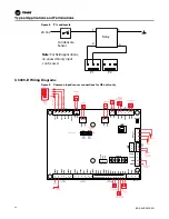
Asterisks (*) Shown Above
• UI1 Relative Humidity Sensor
can be used with dehumidifying
unit instead of a BAS-
communicated valve.
•AI5 Entering Water Temp
Sensor used for auto-
changeover units.
•P1 Condensate Overflow
prevents the condensate drain
from overflowing and
causing water damage to
the building.
Note:
BI4 Frost Detect Input used
to detect freeze conditions
that produce frost on the coil
surface.


