34
RCDA-SVN002C-EN
Wiring
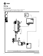
Kit Schematic
Important:
Optional efector flow switch connection at 1TB5 is 115V.
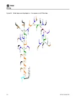
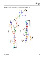
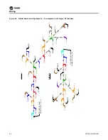
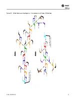
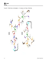
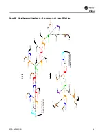
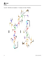
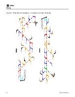
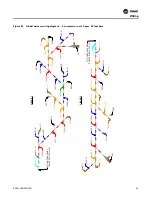
Figure 40.
RTAC UC800/Tracer AdaptiView upgrade schematic
126A
125A
H1
H2
H3
1T
B
5,
1
-8
62
1F
1
5
115V
X1
X3
X2
24V
X4
1T
1
1F
1
7
1T
B
5
,9
-1
6
63
1F
1
6
J2
1U
2
PO
WE
R
SU
PP
L
Y
J11
1
J1
4
14
1
2
3
WB5
1
18C
A
1
17C
A
1
15C
A
J5
1
2
3
4
1
2
3
4
1
2
3
4
J4
J3
162A
161A
WHT
RED
BLK
BLU
GRY
RED
GR
Y/BLK
BLU
GRY
WB
1
/4
1F2
5
2
4
VAC
LI
N
E
UC80
0
U
NIT
C
O
NTROLLER
RED
+2
4
V
D
C
GND
-
+
MBU
S
S
E
RVI
C
E
T
OOL
E
THE
RNET
-
+
-
+
LI
N
K
BLK
BLU
GRY
4
A
2
A
DAPT
IVIE
W
D
IS
PLA
Y
MO
NITOR
USB
P
O
R
T
WB
3
/6
BLK
RED
BLK
BLU
GRY
N
O
TES:
1
.
1F25
FUSE:
1
AMP,
CL
ASS
C
C
F
NQ-R,
600V
LOA
D
IF
AP
PL
ICAB
L
E
,
LI
NK
TO
2U2/
7U2
P
OWER
SUPPLY
NOT
CONNEC
T
ED
SCHEMATI
C
CO
NT
RO
L
S
U
P
G
RA
D
E
Summary of Contents for Tracer AdaptiView
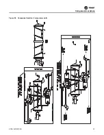
Page 29: ...Figure 36 Component location 2 compressor units Component Locations RCDA SVN002C EN 29 ...
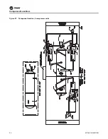
Page 30: ...Figure 37 Component location 3 compressor units Component Locations 30 RCDA SVN002C EN ...
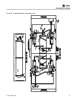
Page 31: ...Figure 38 Component location 4 compressor units Component Locations RCDA SVN002C EN 31 ...
Page 33: ...Component Locations RCDA SVN002C EN 33 Page Left Intentionally Blank ...
Page 50: ......
Page 51: ...Figure 56 Back plate template in actual size 8 00 9 00 6 00 5 00 4X 266 RCDA SVN002C EN 51 ...
Page 52: ...Page left intentionally blank ...
Page 53: ......
Page 54: ......
Page 55: ......


