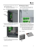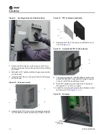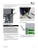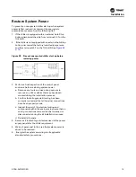
RCDA-SVN002C-EN
11
Installation
Check the Configuration and
Setpoints in the DynaView™
Display/Controller
1. Check the current configuration of the DynaView™ and
confirm that all settings are correct. Make any
necessary changes.
2. Check the current chiller set-points programmed into
the DynaView and confirm that they are all correct for
the unit. Make any necessary changes.
Export the DynaView™
Configuration and Setpoints
Configuration and setpoint values are required to be saved
from the DynaView™ control in order to successfully
configure the upgraded UC800 controller. Using
KestrelView™ on a PC or laptop computer:
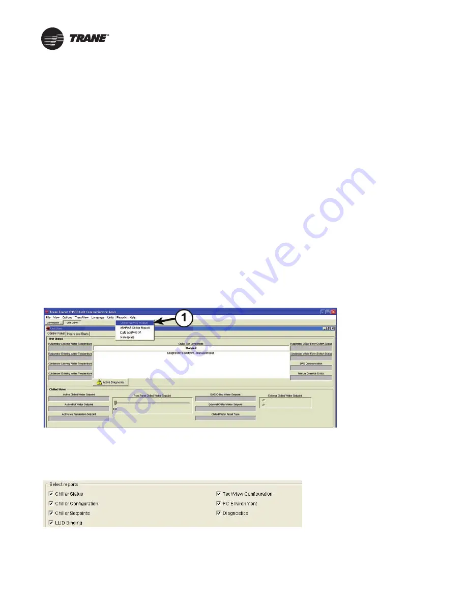
1. Generate a Chiller Service report from the DynaView
with Level 4 active. To do this, click on
Reports Menu
and select
Chiller Service Report
.
Figure 2.
KestrelView screenshot—accessing Chiller Service report
2. Select all reports to ensure that you get a complete
report and convert the report to PDF. The PDF file will
be required to manually copy configuration and
setpoint values with Tracer
®
TU once the Tracer
®
AdaptiView™ display and UC800 are installed.
3. Verify that the PDF report was printed. The PDF report
will be used when configuring the upgraded UC800
controller within Tracer TU.
Summary of Contents for Tracer AdaptiView
Page 29: ...Figure 36 Component location 2 compressor units Component Locations RCDA SVN002C EN 29 ...
Page 30: ...Figure 37 Component location 3 compressor units Component Locations 30 RCDA SVN002C EN ...
Page 31: ...Figure 38 Component location 4 compressor units Component Locations RCDA SVN002C EN 31 ...
Page 33: ...Component Locations RCDA SVN002C EN 33 Page Left Intentionally Blank ...
Page 50: ......
Page 51: ...Figure 56 Back plate template in actual size 8 00 9 00 6 00 5 00 4X 266 RCDA SVN002C EN 51 ...
Page 52: ...Page left intentionally blank ...
Page 53: ......
Page 54: ......
Page 55: ......


