Installation
18
RCDA-SVN002C-EN
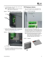
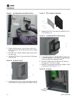
6. Crimp two terminals (X19180041070) to extension
X19051625030 from the TD7 and connect to the “Load”
Side of the transformer. See
.
Figure 24.
TD7 power connection
7. Connect the Ethernet cable from the TD7 to the UC800.
Figure 25.
TD7 communication connection
8. Install the USB Service port in the panel and connect to
the UC800. Install the USB weatherproof cap. See
Figure 26.
USB port installation
9. Secure all cables with the adhesive backed zip ties
provided in the kit. See
.
Figure 27.
Secure all cables
Connect TD7 Power
to Load Side
of Transformer
Connect Ethernet Cable
from TD7 to UC800
Install USB Port
Into Panel with
Weatherproof Cap
and Connect
to UC800
Secure ALL
Cables with
Adhesive
Backed
Zip Ties
Summary of Contents for Tracer AdaptiView
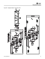
Page 29: ...Figure 36 Component location 2 compressor units Component Locations RCDA SVN002C EN 29 ...
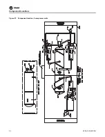
Page 30: ...Figure 37 Component location 3 compressor units Component Locations 30 RCDA SVN002C EN ...
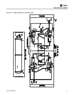
Page 31: ...Figure 38 Component location 4 compressor units Component Locations RCDA SVN002C EN 31 ...
Page 33: ...Component Locations RCDA SVN002C EN 33 Page Left Intentionally Blank ...
Page 50: ......
Page 51: ...Figure 56 Back plate template in actual size 8 00 9 00 6 00 5 00 4X 266 RCDA SVN002C EN 51 ...
Page 52: ...Page left intentionally blank ...
Page 53: ......
Page 54: ......
Page 55: ......

