Operating instructions
4
A70 UG 007 E - 0299
Your new THS thermostat has been
designed to provide precise control and
display of the ambient temperature. It
also displays all the other information
you need concerning your system.
The symbols on the keys and the infor-
mation display format make it a prod-
uct that is easy to understand and use.
It is a good idea to set aside some time
to read these instructions and famil-
iarise yourself with the different func-
tions to get the maximum benefit from
this electronic control system.
General information
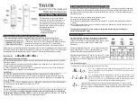
The thermostat normally displays the
ambient temperature, the operating
mode and indicates whether the unit is
cooling or heating. The six keys on the
front panel give you total control of the
equipment.
You can select different heating and
cooling set points for the system, e.g.
21°C for heating and 24°C for cooling.
To increase or decrease the heating and
cooling set points, you only have to
press one key. In addition you can
choose display in °F or °C.
You can also select continuous fan
operation (useful for an air purifier) or
fan operation linked to operation of the
air-conditioning system.
User commands
MODE:
❉
Select the operating mode you want by
pressing the MODE key several times.
❉
- controls the system in cooling
mode only.
(the word "
COOL
" is displayed
for 5 seconds).
- controls the system in heating
mode only (the word "
HEAT
" is
displayed for 5 seconds).
❉
- controls the system in both
heating and cooling modes
(the word "
AUTO
" is displayed
for 5 seconds.
( )
-
forced heating (the word “
EHt
“
is displayed for 5 seconds).
OFF
- stops the thermostat and the
system
COOLING:
❉
Select the temperature the system
must maintain in cooling mode by
pressing the
and
keys. The set
point value is displayed for 5 seconds
with .
HEATING:
Select the temperature the system
must maintain in heating mode by
pressing the
and
keys. The set
point value is displayed for 5 seconds
with .
FAN:
The fan starts automatically when the
system is operating, but this is not indi-
cated on the display unit. To select con-
tinuous operation of the fan press the
key and the screen displays
.
OFF:
When the word “
OFF
“ is displayed, the
system does not operate.
Avoid using the
OFF
mode during peri-
ods of extreme cold, to prevent the risk
of frosting.
AUTO:
❉
In this mode the system operates in
heating and cooling mode. The thermo-
stat changes automatically from one to
the other according to the chosen set
points.
N.B.: The thermostat always leaves
a difference of 1°C between the
heating and cooling set points.
▲
▼
▲
▼