RTWB-SVN01B-E4
11
Installation Mechanical
Isolation pads
The elastomeric pads shipped are
adequate for most installations. For
additional details on isolation
practices, consult an acoustical
engineer for sensitive installations.
Water piping
Piping connections
C
CA
AU
UT
TIIO
ON
N
To prevent equipment damage,
bypass the unit if using an acidic
flushing agent.
Make water piping connections to
the evaporator and condenser.
Isolate and support piping to
prevent stress on the unit. Construct
piping according to local and
national codes. Isolate and flush
piping before connecting it to the
unit.
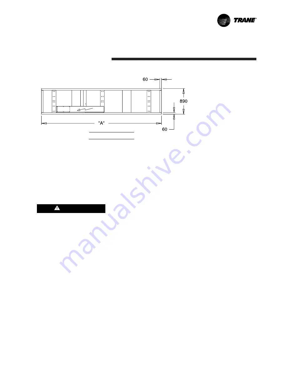
Figure 6 – Isolator pad location
Evaporator water piping
Figure 7 illustrates typical
evaporator piping components.
Components and layout will vary
slightly, depending on the location
of connections and the water
source.
The chilled-water connections are
on the back of the unit, when facing
the control panel.
A vent is provided on the top of the
evaporator at the return end. Be
sure to provide additional vents at
high points in the piping to bleed air
from the chilled-water system.
Install necessary pressure gauges to
monitor the entering and leaving
chilled-water pressures.
To prevent damage to chilled-water
components, do not allow
evaporator pressure (maximum
working pressure) to exceed 10 bar.
Provide shutoff valves in lines to the
gauges, in order to isolate them
from the system when they are not
in use. Use rubber vibration
eliminators to prevent vibration
transmission through the water
lines.
If desired, install thermometers in
the lines to monitor entering and
leaving-water temperatures. Install a
balancing valve in the leaving-water
line to control the balance of the
water flow. Install shutoff valves on
both the entering and leaving-water
lines so that the evaporator can be
isolated for service.
A pipe strainer should be installed in
the entering water line to prevent
water-borne debris from entering the
evaporator.
Dimensions in mm
Size
“A”
207 and 208
2880
210 to 224
4150


