Unit Controls and Sequence of Operation
12
SRV-SVX04B-EN
4. Username & Password
The operator will be prompted by the appearance of
the password screen (Figure 6) on occasions where
secure parameters are attempting to be accessed.
(Contact Rental Services Technical Support if a
password is required.). Then ENTER button will
reverse highlight the character for editing. Use the
arrows buttons as necessary to select the desired
characters. Once the last character has been located
press enter, NOT ANY ARROW, to proceed to the
password window. Press ENTER again to allow editing
again for the password. Once the last character has
been located press enter, NOT ANY ARROW, the “OK”
shall display a dotted box within, press ENTER to
accept and the screen will return to make the selection
without security restriction.
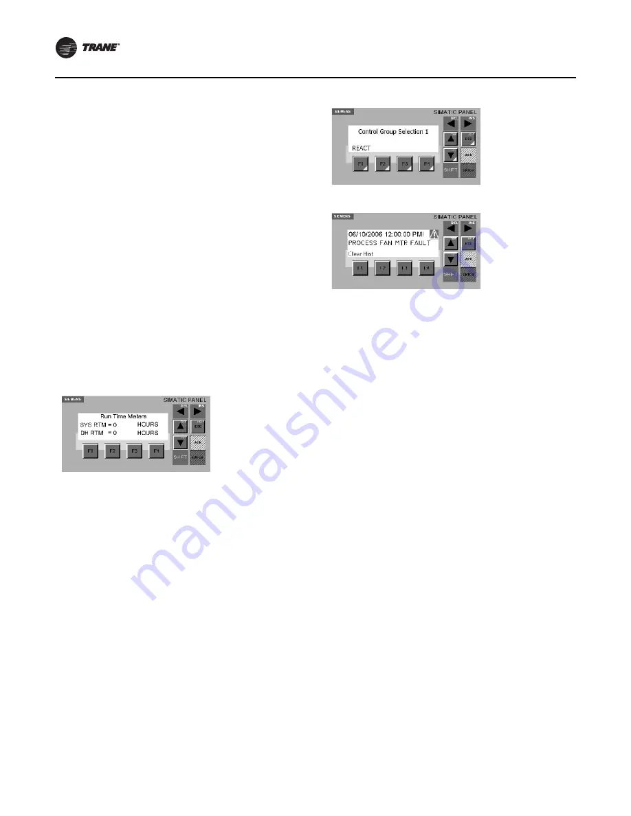
5. Run Time Meter
Pressing the Down Arrow once navigates to this screen
(Figure 7). The Run Time Meter screen displays the
amount of time in hours that the equipment has been
in operation. There is an indication for DH displaying
the amount of time dehumidification has been
requested and in operation. These values, shown in
hours, may vary dependant on the equipment’s
configuration.
Figure 7.
6. Control Group Selection 1*
Pressing F1 (PID) will navigate to this screen (Figure 8).
The OP73 Display may prompt the operator for
Username and Password (figure 9); this must be
entered to proceed (section 7.7). See Section 834 for
information regarding Username and Password. The
Control Group Selection 1 screen displays the various
system loops available on the equipment.
a. Alarms
Pressing F2 (ALM) will navigate to this screen
(Figure 8). The Alarm screen displays the Faults and
Warnings the system encountered during
operation. The triangle with exclamation point will
indicate to the operator when an alarm condition
exists. The current alarm message may be cleared
without clearing the history by pressing the ACK
button.
The Alarm Screen displays and records information
on triggered alarms. Each time an alarm is
triggered, it is added to the Alarm History list
Figure 9, and the last alarm shall be displayed.
Figure 8.
Figure 9.
b. F4 RESET
The operator must press the F4 button to reset a
fault in the PLC; this will clear all system faults and
enable the equipment to be restarted by cycling the
selector switch. The selector switch may also be
used as the system reset by turning it to the off
position and return it to the auto or manual
position. The acknowledge button (ACK) must be
pressed to clear the message and alarm symbol
indication. The system screen will display READY
after a fault has been reset.
c. F1 CLEAR History
The alarm history (Figure 9.) can be viewed by
pressing the down arrow first and both up and
down arrows to scroll the alarms stored. Clearing
the alarm history press F1. It will prompt for the
Username and Password, upon entering the correct
characters the operator has the ability to clear the
history.
Summary of Contents for RSDH0012
Page 13: ...SRV SVX04B EN 13 Fan Curve Figure 10...
Page 14: ...14 SRV SVX04B EN Wiring Diagrams Figure 11 Figure 12...
Page 15: ...Wiring Diagrams SRV SVX04B EN 15 Figure 13 Figure 14...
Page 16: ...Wiring Diagrams 16 SRV SVX04B EN Figure 15 Figure 16...
Page 17: ...Wiring Diagrams SRV SVX04B EN 17 Figure 17 Figure 18...
Page 18: ...Wiring Diagrams 18 SRV SVX04B EN Figure 19 Figure 20...


