Trane FADA Installation & Operation Manual Download Page 10

10

FAXA-SVX01B-EN

Installation

pre-installation
considerations

Service Access

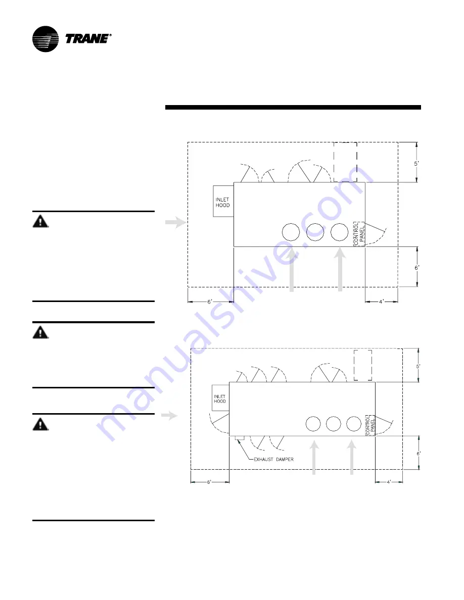
Maintain adequate clearances around
and above the fresh air unit to ensure
proper unit operation and allow sufficient
service access. See Figure I-PC-1 for
recommended clearances. If installing the
unit higher than the typical curb elevation,
field-construct a catwalk around it to
provide safe, easy maintenance access.


WARNING!

Hazardous voltage!

Disconnect electrical power source
and remote disconnects before
servicing unit. Follow proper lockout/
tagout procedures to ensure power
cannot be inadvertently energized.
Failure to do so may cause death or
injury.

Figure I-PC-1. Top view of fresh air unit showing recommended service and code clearances.

service access
for removal of
gas  or electric
heaters

unit without TE wheel

condenser airflow and
compressor maintenance

air path into unit


WARNING!

Disconnect gas supply!

Before servicing unit, FIRST turn off
the gas supply. Failure to turn off the
gas supply can cause death or serious
injury.

WARNING!

Combustible materials!

Maintain proper clearance between
the unit heat exchanger, vent
surfaces, and combustible materials.
Refer to this manual for proper
clearances. Improper clearances can
cause a fire hazard. Failure to
maintain proper clearances can cause
death, serious injury, or property
damage.

unit with TE wheel

condenser airflow

air path into

service
access for
removal of

Summary of Contents for FADA

Page 1: ...FAXA SVX01B EN Installation Operation andMaintenance Packaged Fresh Air Unit For 100 Outdoor Air Applications Models FADA and FAHA BO and later design sequence April 2003...

Page 2: ...ial hazardous situations which if not avoided can cause death or serious injury CAUTION Cautions indicate a potentially hazardous situation which if not avoided may cause minor or moderate injury Also...

Page 3: ...tion 2 General Information 2 Pre installation Considerations 8 Dimensions Weights 15 Mechanical Requirements 33 Electrical Requirements 36 Installation Procedure 40 Pre Startup Requirements 51 Startup...

Page 4: ...8 13 centrifugal fan Digits 21 22 23 Supply fan rpm 037 375 040 400 042 425 045 450 047 475 050 500 052 525 055 550 057 575 060 600 062 625 065 650 067 675 070 700 072 725 075 750 077 775 080 800 082...

Page 5: ...5 650 067 675 070 700 072 725 075 750 077 775 080 800 082 825 085 850 087 875 090 900 092 925 095 950 097 975 100 1000 102 1025 105 1050 107 1075 110 1100 112 1125 115 1150 117 1175 120 1200 122 1225...

Page 6: ...an interface B remote mounted human interface with interprocessor communication bridge module board kit C interprocessor communication bridge module board kit Digit 16 Zone sensor 0 none A zone temper...

Page 7: ...ted filter section with adjustable rack to 4 Standard protective bird screen on inlet hood Traq damper available for airflow measurement Optional return air damper for unoccupied recirculation Non cor...

Page 8: ...nd operating clearances Reference page 10 o Make provisions for correct supply power and note electrical connection knockouts locations on the unit submittals or in the Dimensions and Weights section...

Page 9: ...to submit a claim Note Failure to follow these procedures may result in no reimbursement for damages from the freight company o Do not move damaged material from the receiving location It is the rece...

Page 10: ...to do so may cause death or injury Figure I PC 1 Top view of fresh air unit showing recommended service and code clearances service access for removal of gas or electric heaters unit without TE wheel...

Page 11: ...le toward the top of the curb 2 Attach end rail 1 to side rail 3 using 4 sheet metal screws 3 Align side rail 4 next to side rail 3 and attach crossmember 11 perpendicular to both side rails at the jo...

Page 12: ...9 corner angle 21 6 wood nailer side 10 corner angle 22 6 wood nailer end 11 crossmember 23 6 wood nailer end 12 duct support end rail Standard roof curb assembly units without TE wheel option Typical...

Page 13: ...1 end rail R A E A end 15 duct support end rail 2 end rail S A end 16 duct support side rail R A end 3 side rail 17 duct support side rail R A end 4 side rail 18 duct support side rail E A end 5 side...

Page 14: ...ly exhaust and return duct pen etration in the roof deck To maintain roof integrity and prevent possible property damage do not remove the roof decking from the inside perimeter of the curb Installati...

Page 15: ...M N P withoutTEwheel 031 041 18 10 2 7 4 2 3 10 3 2 10 9 1 11 1 2 1 1 4 1 6 1 4 2 1 2 051 066 19 3 3 5 10 4 1 3 6 1 3 10 1 4 2 4 1 2 1 1 4 3 6 3 4 3 withTEwheel 031 041 24 2 2 7 4 2 3 10 9 1 4 3 2 10...

Page 16: ...A SVX01B EN Installation dimensions weights single dual gas heater options unit with TE wheel indoor side view electric heat version shown unit without TE wheel indoor side view electric heat version...

Page 17: ...FAXA SVX01B EN 17 Installation dimensions weights Unit base plan view duct openings thru base power openings unit sizes 031 040 unit without TE wheel unit with TE wheel...

Page 18: ...18 FAXA SVX01B EN Installation dimensions weights Unit base plan view duct openings thru base power openings unit sizes 051 066 unit with TE wheel unit without TE wheel...

Page 19: ...stallation dimensions weights detail A THRU BASE MAIN POWER WIRING ENTRANCE HOLE 3 000 NOTE DRILL OR PUNCH HOLE IN COVER PLATE FOR SMALLER CONDUIT CONNECTION 3x Fresh air unit control panel detail all...

Page 20: ...TLET OPTION DUAL GAS HEAT ACCESS PANEL EACH HEATER HAS SEPARATE PANEL 16x23 GAS CONNECTION DUAL GAS HEAT EACH HEATER HAS SEPARATE GAS CONNECTIONS NATURAL GAS 250 400 MBH 500 NPT INTERNAL ELECTRIC HEAT...

Page 21: ...FAXA SVX01B EN 21 Installation dimensions weights Exterior features unit sizes 031 040 with TE wheel...

Page 22: ...FILTER AND DAMPER ACCESS DOOR 25x59 SUPPLY FAN ACCESS DOOR 33x54 CONDENSATE DRAIN CONNECTION ELECTRIC HEATER ELECTRICAL PANEL 24x49 OR SINGLE GAS HEAT ACCESS PANEL 16x23 OR FIXED PANEL FOR NO HEAT OPT...

Page 23: ...FAXA SVX01B EN 23 Installation dimensions weights Exterior features for unit sizes 051 066 with TE wheel...

Page 24: ...24 FAXA SVX01B EN Installation dimensions weights Standard curb unit sizes 031 040 without TE wheel 6 WOOD NAILER...

Page 25: ...FAXA SVX01B EN 25 Installation dimensions weights 6 WOOD NAILER Standard roof curb unit sizes 031 040 with TE wheel...

Page 26: ...26 FAXA SVX01B EN Installation dimensions weights 6 WOOD NAILER Standard curb unit sizes 051 66 without TE wheel...

Page 27: ...FAXA SVX01B EN 27 Installation dimensions weights Standard roof curb unit sizes 051 066 with TE wheel 6 WOOD NAILER...

Page 28: ...28 FAXA SVX01B EN Installation dimensions weights Extended height roof curb unit sizes 031 040 without TE wheel 6 WOOD NAILER...

Page 29: ...FAXA SVX01B EN 29 Installation dimensions weights Extended height roof curb unit sizes 031 040 with TE wheel 6 WOOD NAILER...

Page 30: ...30 FAXA SVX01B EN Installation dimensions weights Extended height roof curb unit sizes 051 066 without TE wheel 6 WOOD NAILER...

Page 31: ...FAXA SVX01B EN 31 Installation dimensions weights 6 WOOD NAILER Extended height roof curb unit sizes 051 066 with TE wheel...

Page 32: ...434 494 590 590 666 722 60 100 270 Unit and accessory weights Table I DW 1 Typical unit unit with total energy wheel and roof curb weights unit baseunit totalenergywheelunit roof curb for unit w o TE...

Page 33: ...nit due to increased noise and excessive static losses Use elbows with splitters or turning vanes to minimize static losses Poorly constructed turning vanes may cause airflow generated noise Check tot...

Page 34: ...0 75 0 68 0 63 7 58 0 55 2 52 4 46 7 42 5 38 8 36 2 3 3 068 11000 7700 6250 5300 4750 4300 3900 3700 3450 3250 2950 2650 2450 2280 78 311 218 177 150 135 122 110 105 97 7 92 0 83 5 75 0 69 4 64 6 4 4...

Page 35: ...n pan can restrict the flow of condensate or cause spitting or geysering of the condensate water which can dampen the interior insulation of the air handler and or ductwork creating an opportunity for...

Page 36: ...comp3 D size voltage tons rla lra tons rla lra tons rla lra tons rla lra 031 208 60 3 4 5 15 124 9 0 35 222 14 0 48 337 230 60 3 4 5 15 124 9 0 31 251 14 0 43 376 460 60 3 4 5 8 59 6 9 0 16 117 14 0 2...

Page 37: ...e nameplate MCA value that is the larger of the cooling set 1 or the heating mode MCA calculated above MOP 2 25 x load 1 load 2 load 3 load 4 Select an overcurrent protective device rating equal to th...

Page 38: ...or MCA and MOP calculations one for each power connection MCA1 and MOP1 represent the values calculated for the operation of the compressors and condenser fans For the calculations of MCA1 and MOP1 u...

Page 39: ...8 4 202 1 240 6 460 60 3 38 5 50 5 67 4 84 2 101 0 120 3 066 208 60 3 116 6 155 4 194 3 233 2 277 6 338 6 230 60 3 101 0 134 7 168 4 202 1 240 6 293 5 460 60 3 50 5 67 4 84 2 101 0 120 3 146 7 Note El...

Page 40: ...position it over the roof curb Align the unit base rails with the roof curb 5 Lower the unit onto the curb Make sure the curb gasket remains intact when positioning the unit Center of Gravity and Weig...

Page 41: ...th horizontal axis max slope 1 4 per foot WARNING Improper unit lift Failure to properly lift unit can cause death serious injury or equipment property only damage B A LIFTING POINT A MUST BE ALIGNED...

Page 42: ...lling the unit in its final position following the procedure below 1 Remove the temporary shipping panel from the exhaust exit 2 Locate the shipped with gravity damper in the main filter compartment A...

Page 43: ...e size distancefrom recommended unittocontroller wiring size 0 150feet 22gauge 151 240feet 20gauge 241 385feet 18gauge 386 610feet 16gauge 611 970feet 14gauge Zone Sensor Installation for Temperature...

Page 44: ...44 FAXA SVX01B EN Installation installation procedure Figure I IP 4 Typical zone sensor installation Figure I IP 3 Zone sensor mounting hole locations Junction Mounting to Junction Box Wall Mounting...

Page 45: ...tallation Checklist 1 Ensure operating temperature is within 4 to 131 F 2 Locate the time clock at least 5 feet away from any large electrical contact or machinery to avoid possible electrical interfe...

Page 46: ...ate the service test function at the unit The RHI door has a locking screw to deter access by unauthorized person nel Additionally the RHI can control up to four different units Location Recommendatio...

Page 47: ...n the electrical handy box and secure with the appropriate screws 5 Replace the microprocessor within the enclosure as follows a Verify that the terminal block jumpers are connected properly b Slide t...

Page 48: ...48 FAXA SVX01B EN Installation installation procedure Figure I IP 7 Remote HI mounting holes and knockout locations...

Page 49: ...the bare shield wire off Strip approximately 1 2 inch of insulation from each insulated wire to connect them to the terminal strip at the remote panel Connect the white lead to the positive terminal...

Page 50: ...curb or unit oCheck unit for shipping damage and material shortage Refer to the Receiving Checklist on page 9 oRig the unit Refer to Figure I IP 2 page 41 oPlace the unit on curb and check leveling En...

Page 51: ...ee the Service Access section on page 10 Unit Mounting qRemove shipping brackets on the compressor assembly exhaust and supply fans Component Overview qVerify all fan and motor sheaves are aligned qCh...

Page 52: ...nner bulb seals against the wheel face Follow the procedure below 1 With the wheel stopped move seals as close to the sealing surface as possible but without exceeding grip range of bulb seal and with...

Page 53: ...provided that Tracer Summit is not controlling the module outputs or the generic BAS is not keeping the unit off Figure I S 2 Compressor arrangement for unit sizes 051 066 B C D circuit 2 main A circ...

Page 54: ...oltage L1 L2 ______________ L2 L3 ______________ L1 L3 ______________ L1 ground __________ L2 ground __________ L3 ground __________ Visual observation of the refrigerant circuit Evaporator coil clean...

Page 55: ...tal energy wheel motor nameplate hp ____________ motor nameplate FLA ____________ fan motor amps ____________ fan motor nameplate FLA L1 ____________ L2 ____________ L3 ____________ fan wheel rpm if k...

Page 56: ...aust fan air proving Binary outputs unoccupied mode indicator alarm exhaust fan enable Analog input OA damper minimum position heating option analog output hydronic heat interface LonTalk communicatio...

Page 57: ...olling The HI panel is mounted in the unit s main control panel accessible through the unit s control panel door The optional remote mount version of the human interface RHI panel has all the function...

Page 58: ...or ships with every Packaged Fresh Air unit Additional sensors are also available for order using the accessory model number This zone sensor includes an internal thermistor and should be mounted in t...

Page 59: ...command Integrated Comfort Systems Sensors for FAU Applications Zone temperature sensor w timed override buttons and local setpoint adjustment accessory model number digit 18 A BAYSENS014 Zone temper...

Page 60: ...r as necessary Heating When the outdoor air dry bulb temperature is colder than space conditions require the FAU heats the outdoor air to meet space temperature requirements The Packaged FAU has elect...

Page 61: ...systems are sized for minimum ventilation air only To provide economizer capability on a dedicated outdoor air system the terminal units must have the ability to introduce 100 outdoor air during the...

Page 62: ...int condition is maintained at all load conditions Cooling or Heating Consider Chart O GI 9 If the outdoor air dew point is equal to or below the dew point setpoint the FAU will heat or cool the outdo...

Page 63: ...t dry bulb temperature 3 Design dew point temperature with mean coincident dry bulb temperature The design wet bulb condition typically represents a significantly higher outdoor air enthalpy than the...

Page 64: ...of this simplified version of energy recovery In addition to being more effective from a control standpoint it s also a very simple control method because the total energy wheel only enables when all...

Page 65: ...rying mode the first compressor stage will always remain active This allows condenser reheat when ordered to be available as required during drying operation Additional compressors will be sequenced t...

Page 66: ...RH setpoint Supply air reheat functions are active to maintain the supply air reheat setpoint Supply air reheat reset functions are active and reset based on unoccupied zone setpoints Exhaust fan oper...

Page 67: ...2 Unoccupied Sequence In unoccupied mode the fan stops and the OA damper closes Zone Temp Control No Dehumidification Unit 1 Occupied Sequence During occupied mode the primary function of the unit is...

Page 68: ...5 vdc signal to any of the GBAS inputs to access the following inputs and outputs listed in the paragraphs below GBAS analog inputs These four analog inputs can be configured to any of the following 1...

Page 69: ...ith OA RH reference must be ordered to utilize either comparative enthalpy or reference enthalpy control Emergency Stop Input A binary input is provided on the unit s RTM module board for installation...

Page 70: ...70 FAXA SVX01B EN Maintenance general information Component arrangement unit size 031 040 unit without TE wheel unit with TE wheel...

Page 71: ...FAXA SVX01B EN 71 Maintenance general information unit without TE wheel Component arrangement unit size 051 066 unit with TE wheel...

Page 72: ...72 FAXA SVX01B EN Maintenance general information Total energy wheel cassette locations typical indoor side views unit size 031 unit size 040 unit size 051 unit size 066...

Page 73: ...68 2 168 2 168 2 168 tubediameter in surface 0 5 enhanced 0 5 enhanced 0 5 enhanced 0 5 enhanced Condensercoil reheatoutdoor size ft2 5 35 7 29 9 38 9 38 rows fin series 2 168 2 168 2 168 2 168 tubedi...

Page 74: ...age to the coil WARNING Hazardous chemicals Coil cleaning agents can be either acidic or highly alkaline Handle chemical carefully Ensure proper handling by wearing goggles or face shield chemical res...

Page 75: ...ack are capped and can be removed during cleaning Replace caps to avoid air bypass The single draw hole located upstream of the outside air filters should be utilized for draining during cleaning Ensu...

Page 76: ...aft is parallel Figure M MP 3 Fan shaft and motor sheave alignment putting the system back into service 8 Determine and correct the cause of any microbial contamination 9 Be careful that the contamina...

Page 77: ...accelerate belt wear and possibly cause shaft failure Recommended belt tension range values are on the unit fan scroll To access the fan scroll face the right hand side of the deflection belt span 64...

Page 78: ...Federal Clean Air Act or other state or local codes as appropriate After removing refrigerant use dry nitrogen to bring the system back to atmospheric pressure before opening for repairs Refrigerant m...

Page 79: ...e the tank pressure when removing refrigerant use only warm water or heat blankets to raise the tank temperature Do not exceed 150 F Do not under any circumstances apply direct flame to any portion of...

Page 80: ...in 5 Check and record operating pressures 6 Inspect and clean total energy wheel as needed Semi Annual Maintenance 1 Verify the fan motor is properly aligned and bolted tight to the motor frame 2 Lub...

Page 81: ...her properly trained individual perform these tasks Failure to follow all electrical safety precautions when exposed to live electrical components can cause death or serious injury Operating Procedure...

Page 82: ...a 70 maintenance periodic checklists 77 maintenance procedures 71 monthly checklist 77 mounting the remote human inter face RHI panel 47 O operating procedures 78 overview of manual 2 P packaged FAU o...

Page 83: ......

Page 84: ...ure Order Number File Number Supersedes Stocking Location Trane has a policy of continuous product improvement and reserves the right to change design and specifica tions without notice Only qualified...

Reviews: