General unit characteristics
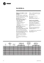
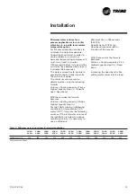
For minimum clearance, consult the
certified submittals, which are
available on request from your Trane
sales office.
Unit nameplate
The unit nameplate gives the
complete model reference numbers.
The unit power rating is shown, and
power supplies should not deviate
by more than 5 % from the rated
power.
Compressor motor amperage is
shown in box I.MAX.
The customer's electrical installation
must be able to withstand this current.
Installation instructions
Foundations
No special foundations are required,
provided the supporting surface is
flat and level, and can withstand the
weight or the unit.
Isolating rubber pads
They are supplied as standard with
the machine, and should be placed
between the supporting floor and
the unit to isolate from the ground.
- 4 pads for the sizes 200 - 490
- 6 pads for the sizes 500 - 925
- Trane does not recommend to
install spring isolators.
Water drain hole
For units with an hydraulic module,
condensates are to be collected
below the pump and drained away.
Clearance
Respect recommended clearance
around the unit to allow
maintenance operation to take place
without obstruction and
recommended clearance around
condenser.
Caution
Unit operation is function of the air
temperature. Any recycling of the air
fed out by the fans will increase the
air intake temperature over the
condenser fins and can result in high
pressure cut-out.
In this case the standard operating
conditions and performance are
modified.
Operation of the unit may be
affected by an increase in air
temperature on the condenser. When
the units are positioned in a windy
area, avoid all the risks of air-cooled
recycling. Refer to certified
drawings.
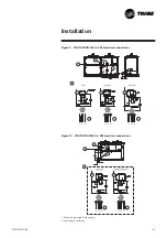
Figure 1 - Handling - units without
Buffer tank
Note: The plates welded at the end of the bases
must not be used for handling.
Figure 2 - Handling - units with
buffer tank
CG-SVX01C-E4
15
Installation


