background image

6

CG-SVX01C-E4

General Data

Table 1 - CGAN Cooling only - Standard version - R407C

CGAN

CGAN

CGAN

CGAN

CGAN

CGAN

200

250

300

400

450

490

Eurovent Performances (1)

Net Cooling Capacity

(kW)

50.7

62.5

76.2

102.8

121.8

132.3

Total Power input in cooling

(kW)

19.1

24.4

28.8

38.7

43.6

50.5

Water pressure drop

(kPa)

29

33

38

46

43

44

Pressure available (5)

(kPa)

195

180

173

139

195

181

Main Power supply

400/3/50

400/3/50

400/3/50

400/3/50

400/3/50

400/3/50

Units Amps

Nominal (4)

(A)

47

57

69

89

102

111

Start-up Amps

(A)

148

203

215

236

327

336

Short circuit unit capacity

(kA)

10

10

10

10

10

10

Max supply cable size

(mm²)

16

35

35

95

95

95

Min supply cable size

(mm²)

10

16

16

50

50

50

Compressor
Number

2

2

2

3

2

2

Type

Scroll

Scroll

Scroll

Scroll

Scroll

Scroll

Model

(10T+10T)

(10T+15T)

(15T+15T)

(15T+15T+10T)

(20T+25T)

(25T+25T)

Rated Amps (4)

(A)

19+19

19+28.5

28.5+28.5

28.5+28.5+19

38+47

47+47

Locked rotor Amps (2)

(A)

120

175

175

175

272

272

Motor RPM

(rpm)

2900

2900

2900

2900

2900

2900

Power factor

0.84

0.85

0.85

0.85

0.87

0.87

Sump Heater (2)

(W)

100

160

160

160

150

150

Evaporator

Number

1

1

1

1

1

1

Type

Brazed plate

Brazed plate

Brazed plate

Brazed plate

Brazed plate

Brazed plate

Model

V200x38

V200x46

V200x54

V200x72

AC 120-108 EQ

AC 120-120 EQ

Water volume (total)

(l)

5.3

6.8

8.2

10.5

11.3

12.6

Antifreeze Heater

(W)

115

115

115

115

115

115

Unit Water Connections

Male ISO R7

Male ISO R7

Male ISO R7

Male ISO R7

Male ISO R7

Male ISO R7

Water Connections Diameter

2"

2"

2 1/2"

2 1/2"

2 1/2"

2 1/2"

Coil

Type

Slit Fin

Slit Fin

Slit Fin

Slit Fin

Slit Fin

Slit Fin

Length

(mm)

2489

2489

2896

2896

2896

2896

Height

(mm)

1422

1422

1422

1626

1626

1626

Face Area (3)

(m²)

3.54

3.54

4.12

4.71

4.71

4.71

Rows

2

3

3

3

4

4

Fins per foot 

(fpf)

204

180

180

180

168

168

Fan

Type

Propeller

Propeller

Propeller

Propeller

Propeller

Propeller

Number

2

2

3

3

3

3

Diameter

(mm)

710

710

710

800

800

800

Drive type

Direct drive

Direct drive

Direct drive

Direct drive

Direct drive

Direct drive

Air flow

(m

3

/h)

20200

19100

26300

37300

37100

37100

Number  of  motors

2

2

3

3

3

3

Motor HP (2)

(kW)

0.57

0.57

0.57

1.05

1.05

1.05

Rated Amps (2)

(A)

1.5

1.5

1.5

2.4

2.4

2.4

Motor RPM

(rpm)

700

700

700

680

680

680

Dimensions

Height (6)

(mm)

1897

1897

1897

2074

2074

2074

Length

(mm)

2800

2800

3200

3200

3200

3200

Width

(mm)

1100

1100

1100

1100

1100

1100

Operating Weight

(kg)

748

842

968

1143

1267

1292

Shipping Weight

(kg)

743

834

954

1124

1260

1284

System Data

Number  of  refrigerant  circuits

1

1

1

1

1

1

Capacity steps

2

2

2

2

2

2

Minimum capacity

(%)

50

40/60

50

37/63

37/63

37/63

Refrigerant Charge (3)

Circuit  A

(kg)

13

18

21

24

28

28

Circuit  B

(kg)

-

-

-

-

-

-

(1) at Eurovent Conditions (Evap 12°C/7°C - Air. 35°C)
(2) per motor
(3) per circuit
(4) Max rated conditions.
(5) Dual Pump Option
(6) For units with HESP option, contact your local sales office

Summary of Contents for AquaStream2 CGAN 200

Page 1: ...Installation Operation Maintenance Cooling only CGAN 200 250 300 400 450 490 500 600 700 800 900 925 Reversible CXAN 200 250 300 400 450 490 500 600 700 800 900 925 CG SVX01C E4 ...

Page 2: ...ion of this equipment The services of a qualified technician should be employed through the medium of a maintenance contract with a reputable service company Read this manual thoroughly before unit start up Units are assembled pressure tested dehydrated charged and run tested before shipment Warnings and cautions Warnings and Cautions appear at appropriate sections throughout this manual Your pers...

Page 3: ... precise analysis made by a specialized laboratory If this condition is not respected the manufacturer warranty could be cancelled Reception On arrival inspect the unit before signing the delivery note Reception in France only In case of visible damage The consignee or the site representative must specify any damage on the delivery note legibly sign and date the delivery note and the truck driver ...

Page 4: ... well as on preventive maintenance which reduces the cost of owning the unit by avoiding serious and costly breakdown Maintenance contract It is strongly recommended that you sign a maintenance contract with your local Service Agency This contract provides regular maintenance of your installation by a specialist in our equipment Regular maintenance ensures that any malfunction is detected and corr...

Page 5: ...g 15 Minimal installation water content 18 Water treatment 20 Antifreeze protection 20 Electrical connections 20 General start up Preparation 22 Start up 22 Operation Control and unit operation 27 Weekly start up and week end shutdown 27 Start up and seasonal shutdown 27 Maintenance Maintenance instructions 28 Installation checklist 29 Troubleshooting guide 30 ...

Page 6: ... 6 Antifreeze Heater W 115 115 115 115 115 115 Unit Water Connections Male ISO R7 Male ISO R7 Male ISO R7 Male ISO R7 Male ISO R7 Male ISO R7 Water Connections Diameter 2 2 2 1 2 2 1 2 2 1 2 2 1 2 Coil Type Slit Fin Slit Fin Slit Fin Slit Fin Slit Fin Slit Fin Length mm 2489 2489 2896 2896 2896 2896 Height mm 1422 1422 1422 1626 1626 1626 Face Area 3 m 3 54 3 54 4 12 4 71 4 71 4 71 Rows 2 3 3 3 4 ...

Page 7: ...e Heater W 180 180 180 180 180 180 Unit Water Connections Male ISO R7 Male ISO R7 Male ISO R7 Male ISO R7 Male ISO R7 Male ISO R7 Water Connections Diameter 2 1 2 2 1 2 3 3 3 3 Coil Type Slit Fin Slit Fin Slit Fin Slit Fin Slit Fin Slit Fin Length mm 2489 2896 2896 2896 2896 2896 Height mm 1422 1422 1626 1626 1626 1626 Face Area 3 m 3 54 4 12 4 71 4 71 4 71 4 71 Rows 3 3 3 3 4 4 Fins per foot fpf ...

Page 8: ...15 115 115 115 115 115 Unit Water Connections Male ISO R7 Male ISO R7 Male ISO R7 Male ISO R7 Male ISO R7 Male ISO R7 Water Connections Diameter 2 2 2 1 2 2 1 2 2 1 2 2 1 2 Coil Type Slit Fin Slit Fin Slit Fin Slit Fin Slit Fin Slit Fin Length mm 2489 2489 2896 2896 2896 2896 Height mm 1422 1422 1422 1626 1626 1626 Face Area 3 m 3 54 3 54 4 12 4 71 4 71 4 71 Rows 2 3 3 3 4 4 Fins per foot fpf 204 ...

Page 9: ...0 180 180 180 180 180 Unit Water Connections Male ISO R7 Male ISO R7 Male ISO R7 Male ISO R7 Male ISO R7 Male ISO R7 Water Connections Diameter 2 1 2 2 1 2 3 3 3 3 Coil Type Slit Fin Slit Fin Slit Fin Slit Fin Slit Fin Slit Fin Length mm 2489 2896 2896 2896 2896 2896 Height mm 1422 1422 1626 1626 1626 1626 Face Area 3 m 3 54 4 12 4 71 4 71 4 71 4 71 Rows 3 3 3 3 4 4 Fins per foot fpf 180 180 180 1...

Page 10: ...ed plate Brazed plate Water volume total l 5 3 6 8 8 2 10 5 10 5 10 5 Antifreeze Heater W 115 115 115 115 115 115 Unit Water Connections Male ISO R7 Male ISO R7 Male ISO R7 Male ISO R7 Male ISO R7 Male ISO R7 Water Connections Diameter 2 2 2 1 2 2 1 2 2 1 2 2 1 2 Coil Type Plate Fin Plate Fin Plate Fin Plate Fin Slit Fin Slit Fin Length mm 2489 2489 2896 2896 2896 2896 Height mm 1422 1422 1422 162...

Page 11: ...e Brazed plate Brazed plate Water volume total l 17 2 19 8 25 6 29 0 35 7 35 7 Antifreeze Heater W 180 180 180 180 180 180 Unit Water Connections Male ISO R7 Male ISO R7 Male ISO R7 Male ISO R7 Male ISO R7 Male ISO R7 Water Connections Diameter 2 1 2 2 1 2 3 3 3 3 Coil Type Plate Fin Plate Fin Plate Fin Plate Fin Plate Fin Slit Fin Length mm 2489 2896 2896 2896 2896 2896 Height mm 1422 1422 1626 1...

Page 12: ...azed plate Brazed plate Water volume total l 5 3 6 8 8 2 10 5 11 3 12 6 Antifreeze Heater W 115 115 115 115 115 115 Unit Water Connections Male ISO R7 Male ISO R7 Male ISO R7 Male ISO R7 Male ISO R7 Male ISO R7 Water Connections Diameter 2 2 2 1 2 2 1 2 2 1 2 2 1 2 Coil Type Plate Fin Plate Fin Plate Fin Plate Fin Slit Fin Slit Fin Length mm 2489 2489 2896 2896 2896 2896 Height mm 1422 1422 1422 1...

Page 13: ...Brazed plate Brazed plate Water volume total l 17 2 19 8 25 6 29 0 35 7 35 7 Antifreeze Heater W 180 180 180 180 180 180 Unit Water Connections Male ISO R7 Male ISO R7 Male ISO R7 Male ISO R7 Male ISO R7 Male ISO R7 Water Connections Diameter 2 1 2 2 1 2 3 3 3 3 Coil Type Slit Fin Slit Fin Slit Fin Slit Fin Slit Fin Slit Fin Length mm 2489 2896 2896 2896 2896 2896 Height mm 1422 1422 1626 1626 162...

Page 14: ...2 1 2 2 1 2 2 1 2 2 1 2 3 3 3 3 Expansion tank volume L 25 25 25 25 25 25 35 35 35 35 35 35 User volume expansion capacity 1 L 1000 1000 1000 1000 1000 1 000 1400 1400 1400 1400 1400 1400 Antifreeze heater W 150 Piping material Steel Hydraulic Module Weight kg 103 103 108 108 108 108 110 110 114 114 189 189 Water tank volume Option L 370 370 410 410 410 410 570 570 570 570 570 570 Water tank addit...

Page 15: ...s 500 925 Trane does not recommend to install spring isolators Water drain hole For units with an hydraulic module condensates are to be collected below the pump and drained away Clearance Respect recommended clearance around the unit to allow maintenance operation to take place without obstruction and recommended clearance around condenser Caution Unit operation is function of the air temperature...

Page 16: ... 3400 3400 3400 3400 3400 3400 Table 7 Shipping weights CGAN CGAN CGAN CGAN CGAN CGAN CGAN CGAN CGAN CGAN CGAN CGAN CXAN CXAN CXAN CXAN CXAN CXAN CXAN CXAN CXAN CXAN CXAN CXAN 200 250 300 400 450 490 500 600 700 800 900 925 Without hydraulic module CGAN kg 743 834 954 1124 1260 1284 1588 1778 2030 2181 2344 2377 CXAN kg 773 864 996 1136 1272 1296 1650 1860 2114 2271 2434 2467 Additional weight for...

Page 17: ...ithout hydraulic module and buffer tank typical water circuit Figure 7 Unit with hydraulic module and buffer tank typical water circuit 1 Pressure gauges show entering and leaving water pressure 2 pressure ports are available inside of the unit see item 1 in figure 5 2 Balancing valve adjusts water flow 3 Air purge allows to remove the air from the water circuit during fill up 4 Stop valves isolat...

Page 18: ... time 120 seconds Specific heat 4 18 kJ kg Dead band recommended 3 C Dead band calculation Dead band Biggest compressors step tonnage Total tonnage X Water temperature difference entry leaving allowed water loop temperature fall Minimum allowed temperature fall 1 5 C Minimum dead band calculation table versus the targeted water temperature deltaT It is preferable to have a higher dead band than th...

Page 19: ...he minimum time between two starts is 5 minutes 300 seconds The water volume has to be able to provide the cooling capacity while the unit is shut down The minimum volume can be determined by using the following formula Volume Cooling capacity xTime x highest capacity step Specific heat Dead band With these values the formula becomes Volume Cooling capacity X 9 56 x highest capacity step For the C...

Page 20: ...all into the starter panel or electric components Relays contactors terminals and control wiring should be covered and protected before power supplies are connected 2 Install power supply cabling as shown in wiring diagram Adequate cable gland should be chosen ensuring no foreign bodies enter the electrical housing or components Caution 1 Cabling must comply with standards in force The type and lo...

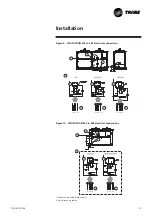
Page 21: ...Field supply 2 Unit disconnect switch A A L1 L2 L3 L1 L2 L3 L1 L2 L3 1 1 1 1 2 2 2 2 L1 L2 L3 L1 L2 L3 A A 2 1 1 2 2 1 Installation Figure 9 CGAN CXAN 200 to 490 electrical connections Figure 10 CGAN CXAN 500 to 925 electrical connections ...

Page 22: ...th water pressure test carried out and air purged Chilled water circuit must be rinsed Check the presence of water strainer ahead of evaporator The strainers must be cleaned after 2 hours of pumps operation Check the thermometers and manometers position Check chilled water pumps interconnection to control panel Ensure that the isolation resistance of all power supply terminals to ground complies w...

Page 23: ...rranty to apply any start up carried out directly by the customer must be recorded in a detailed report which must be sent as soon as possible to the nearestTrane office Do not start up a motor whose insulation resistance is less than 2 meghoms Phase imbalance should not be greater than 2 The voltage supplied to motors should be within 5 of the rated voltage on the compressor nameplate Excessive e...

Page 24: ...7 2 09 212 193 2 54 207 191 3 44 191 176 3 89 232 221 4 22 225 213 2 18 205 186 2 68 191 177 3 27 185 171 4 43 160 142 5 00 213 200 5 43 200 186 2 42 195 179 2 98 180 166 3 63 174 158 4 92 139 121 5 55 201 187 6 03 186 171 2 66 185 171 3 28 168 154 3 99 160 144 5 41 116 97 6 11 188 173 6 63 170 154 3 15 164 149 3 87 141 126 4 72 128 110 6 40 64 44 7 22 159 141 7 84 130 11 3 39 152 137 4 17 126 109...

Page 25: ...400 pump curve 1 Single pump 2 Dual pump Figure 13 CGAN CXAN 450 800 pump curve 1 Single pump 2 Dual pump General start up 0 5 10 15 20 25 0 10 20 30 40 50 60 70 80 1 2 Hm 1 Single pump 2 Dual pump Figure 14 CGAN CXAN 900 925 pump curve m3 h ...

Page 26: ... C 6 C 4 C 2 C 0 C 2 C 4 C 0 5 10 15 20 25 30 35 40 45 10 C 8 C 6 C 4 C 2 C 0 C 2 C 4 C A relief valve is located at pump suction limiting water circuit pressure at 3 bar Nitrogen pressure inside of the expansion tank must be equal to the geometric height of the installation 0 5 bar in order to avoid air entering in the water circuit Expansion tank must be inflated with nitrogen Pressure must be c...

Page 27: ...eck operation of machines compare conditions of operation against original commissioning data Stop the unit following procedure described in the CH532 controller user guide Ensure that all safeties are taken to prevent frost damages during negative ambient temperature Fill out the visit log sheet and review with the operator Do not put the general disconnect switch to off except if the unit is dra...

Page 28: ...nsducer Check operation of all safety devices Inspect contacts and tighten terminals Megger the motor compressor windings Record operating pressures temperatures amperages and voltage Carry out leak test Check configuration of unit control module Carry out oil analysis Change the oil as required based upon results of the oil analysis Check operation of machines compare conditions of operation agai...

Page 29: ...or Check presence of air purge valve Check rinsing and filling of chilled water pipes Check water pump s contactor interconnected to control panel Check water flow Check chilled water pressure drop or unit available pressure units with hydraulic module Check for leaks in chilled water pipes ELECTRICAL EQUIPMENT Check installation and rating of mains power switch fuses Check electrical connections ...

Page 30: ...d up Problem causes Motor burned out Coil burned out or broken contacts a Power cut b Main power supply switched off Fuse blown Voltage too low Regulation circuit open Compressor sticking damaged or sticking components Discharge pressure too high Discharge pressure too high a Voltage too low b Cooling demand too high or condensing temperature too high Not enough cooling fluid Water flow to evapora...

Page 31: ...re higher than specified for unit Excess cooling demand on evaporator a Expansion valve too far open b Expansion valve locked in open position Filter drier clogged Expansion valve bulb has lost its refrigerant Expansion valve obstructed Excessive pressure drops through evaporator Low water flow rate Action recommended Check thermal insulation and air tightness of areas requiring air conditioning C...

Page 32: ...ht to change design and specifications without notice Only qualified technicians should perform the installation and servicing of equipment referred to in this publication Literature Order Number CG SVX01C E4 Date 0805 Supersedes CG SVX01B E4_0204 Literature Stocking Location Europe www trane com For more information contact your local sales office or e mail us at comfort trane com ...

Reviews: