background image

BAS-SVX10F-EN

17

Installation and Configuration: Display Sensor

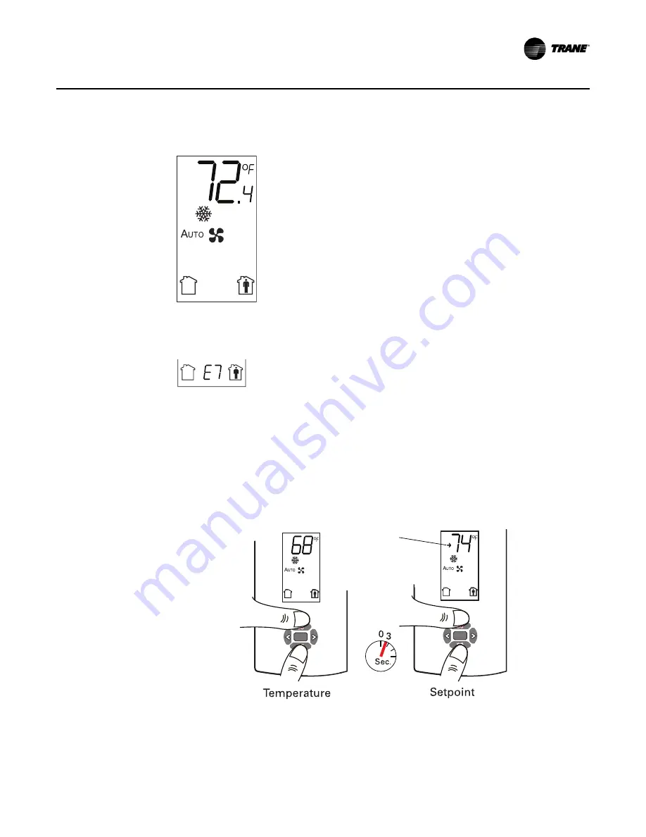
The following example shows a configured display in operating mode.  

If an error code exists, it appears at the bottom of the display between the occupancy symbols, 
as shown below. See 

“Error codes,” p. 31

, for error code definitions.

Optional Configuration Features

Displaying Setpoint or Temperature

You can configure the sensor to display either the temperature (default) or setpoint. To select either 
option:

1. Verify that the sensor is in operating mode and at the home screen.

2. Press the up and down arrows for 3 seconds. The arrow indicates setpoint display, as shown 

in the illustration.

Locking or Unlocking Settings

You can lock or unlock the setpoint, system, or fan setting to prevent changes.

To lock or unlock a setting:

Display shows the following:

Temperature units (Fahrenheit)

Temperature resolution to tenths of a degree

System setting: Cooling

Fan setting: Auto

Occupied/unoccupied option enabled

Arrow 
indicates 
setpoint is 
shown on 
display

Summary of Contents for X1316105702

Page 1: ...ng up and servicing of heating ventilating and air conditioning equipment can be hazardous and requires specific knowledge and training Improperly installed adjusted or altered equipment by an unquali...

Page 2: ...the same potential impact to the environment Trane advocates the responsible handling of all refrigerants including industry replacements for CFCs and HCFCs such as saturated or unsaturated HFCs and H...

Page 3: ...SHA NFPA 70E or other country specific requirements for arc flash protection PRIOR to servicing the unit NEVER PERFORM ANY SWITCHING DISCONNECTING OR VOLTAGE TESTING WITHOUT PROPER ELECTRICAL PPE AND...

Page 4: ...20 Mounting the Back Plate 20 Installing the COMM Module optional 23 Changing the Setpoint Thumb Wheel optional 24 Wiring the Sensor 24 Replacing the Cover 25 Operation 26 Changing Temperature Settin...

Page 5: ...ult Modes of Operation 32 Measuring Output Resistance 33 Display Sensors 33 All Models Other Than the Display Sensor 33 Cleaning the Sensor 35 Replacing the Thumb Wheel 35 Wiring Diagrams 36 Temperatu...

Page 6: ...vice tool for system communication Must be ordered separately Hot cold setpoint thumb wheel Optional accessory allows selecting a temperature setpoint by color red blue for hot cold on thumbwheel rath...

Page 7: ...f Auto Heat No No X1379083701 BAYSENS108A SEN01513 Dual Auto High Cool Off Auto Heat No Yes 4 X1379084601 BAYSENS110A SEN01522 Single Auto High Cool Off Heat No No X1379083901 BAYSENS106A SEN01515 Sin...

Page 8: ...n details The dimensions are the same for all models 2 9 in 73 5 cm 1 08 in 27 5 mm 4 68 in 118 9 mm 1 45 in 36 8 mm 0 63 in 15 9 mm 0 31 in 8 mm 0 12 in 3 mm TYP R 07 in R1 9 mm 3 39 in 86 mm 2 48 in...

Page 9: ...fic areas to reduce accidental damage or tampering Height Requirements The recommended maximum mounting height is 54 inches from the bottom of the back plate to the floor If a parallel approach by a p...

Page 10: ...ler that there is continuity between the sensor location and the controller and that the wires are accurately labeled or identified by color Mounting the Back Plate WARNING Hazardous Voltage Disconnec...

Page 11: ...BAS SVX10F EN 11 Installation and Configuration Display Sensor 3 Feed the wires through the opening in the back plate...

Page 12: ...To wire the sensor to the unit controller 1 Ensure that the wires are connected to the appropriate terminals at the unit controller Note Ensure that the GROUND terminal 10 and the SIGNAL COMMON termi...

Page 13: ...tion Display Sensor 6 Push the excess wire into the wall cavity and plug it with nonflammable insulation to prevent drafts from affecting the sensor Important Do not coil excess wire inside the back p...

Page 14: ...he sensor is in configurationmode a wrench symbol appears on the display and the menus are separated by lines as illustrated below 1 Press the center button on the keypad to begin the configuration pr...

Page 15: ...grees Setpoint Deadband available for dual setpoint system only Note Deadband refers to the minimum difference between the heating and cooling setpoints System a Single setpoint System continued b Dua...

Page 16: ...sed for 10 minutes Fan Note Not all fan options are available for all systems Occupancy timed override Setting Configuration options auto off low med high auto off low high auto off off high on off lo...

Page 17: ...r the temperature default or setpoint To select either option 1 Verify that the sensor is in operating mode and at the home screen 2 Press the up and down arrows for 3 seconds The arrow indicates setp...

Page 18: ...the down arrow to select the fan menu Use the left or right arrow to choose the setting Fan menu 3 Press the left and right arrows for 4 seconds The lock symbol will appear on the display to indicate...

Page 19: ...BAS SVX10F EN 19 Installation and Configuration Display Sensor 2 Secure the cover by installing the security screw into the bottom of the cover Security screw...

Page 20: ...sensor location and the wire is accessible through the hole The technician should assume that the wires are attached to the appropriate unit controller that there is continuity between the location an...

Page 21: ...ving the cover 3 Remove the circuit board by pressing the thumb catch on the left side of the board Use the terminal block to lift the circuit board from the back plate Terminal Thumb catch 4 Feed the...

Page 22: ...h the opening in the circuit board 8 Replace the circuit board by sliding the right side of the board under the two catches on the right side of the back plate while aligning slot on board with tab on...

Page 23: ...a local RJ22 connection to a Trane service tool for maintenance use It must be ordered separately Install the COMM module before wiring the sensor 1 Slide the two cutouts on the right side of the COMM...

Page 24: ...curely onto the back plate 3 Rotate the replacement thumb wheel until the stop is opposite the flat portion of the potentiometer Push down on the thumb wheel until the ribs touch the potentiometer Aft...

Page 25: ...Sensor Replacing the Cover To replace the cover 1 Hook the cover over the top of the back plate Apply light pressure to the bottom of the cover until it snaps in place 2 Secure the cover by installing...

Page 26: ...d ChangingHeatingand Cooling Temperature Settings dual setpoint systems only p 30 Changing System Settings To change system settings For sensors with system thumb wheels located on the upper left side...

Page 27: ...with Occupied Unoccupied buttons To select temporary occupancy press the Occupied button Figure 2 for 0 2 6 seconds The following occurs Space temperature output is driven to 10 nominal The output gen...

Page 28: ...support occupancy and must be in operating mode see Configuring the Display Sensor p 13 To initiate a service pin request 1 With the sensor in operating mode navigate to the occupancy menu 2 Press the...

Page 29: ...is communicated Double star A value of 44 6 F 7 C is communicated Figure 4 Star Double star on thumb wheel Display Sensor The display sensor supports the star and double star functions if the sensor i...

Page 30: ...and Cooling Temperature Settings dual setpoint systems only Some systems allow you to select both heating and cooling room temperature settings If your system has this option this symbol appears when...

Page 31: ...icates fan speed 3 high 2 medium 1 low The example shown indicates a fan on high speed Not all systems offer all three speeds Indicates fan is Off Requesting Temporary Occupancy Select to request occu...

Page 32: ...normal heating operation Blinks to indicate a heating system failure System LED green The green system LED indicates the state of the system Stays on solid to during normal operation Blinks to indicat...

Page 33: ...Measure between the SYS FAN MODE terminal 4 and the SIGNAL COMMON terminal 2 Compare resistance measurements to those in Table 2 p 34 NOTICE Potential Equipment Damage Because the output circuits are...

Page 34: ...setpoint systems Cooling setpoint varies 10 at 70 F 21 1 C varies at 110 at endpoints of scale Heating setpoint varies 20 at 70 F 21 1 C varies at 120 at endpoints of scale 34 BAS SVX10F EN Maintenan...

Page 35: ...cloth and gently wiping the face including the buttons and LCD display Use of a pre moistened towelette designed for lens or screen cleaning is also acceptable Avoid inadvertent pressing buttons on se...

Page 36: ...270 3435 B Zone temperature Signal common Setpoint 1 2 3 Calibration potentiometer Pot 2 see Note NOTE POT 1 and POT2 are factory calibrated Field adjustment voids warranty Zone temperature Signal com...

Page 37: ...tor 10 k at 25 C W 1 2 4 Calibration Pot 1 see Note 1 RT1 Note 1 Pot 1 is factory calibrated Field adjustment voids warranty 3 R1 4 87 kW R2 2 32 kW Auto Off R11 zero W Signal common Cool setpoint CSP...

Page 38: ...temperature Mode System switch TB1 Dwg source X39641098 01 X1379085101 Timed override Cancel SW4 R9 1 5 kW Timed override On SW3 Thermistor 10 k at 25 C W 1 2 4 Calibration Pot 1 see Note 1 RT1 Note 1...

Page 39: ...Pot 5 1 kW Fan SW1 Dwg source X39641088 01 X1379084101 Timed override Cancel SW4 R9 1 5 kW Timed override On SW3 Thermistor 10 k at 25 C W 1 2 4 Calibration Pot 1 see Note 1 RT1 Note 1 Pot 1 is factor...

Page 40: ...CSP Heat Setpoint HSP Zone temperature TB1 Mode Sys Fan switch System SW1 Fan SW2 Cool setpoint Pot 4 1 k Dwg source X39641094 01 RT1 thermistor 10 k at 25 C W Temperature setpoint Pot 5 1 kW 1 2 4 Ca...

Page 41: ...g source X39641084 01 RT1 thermistor 10 k at 25 C W 1 2 4 Calibration Pot 1 see Note 1 R7 3 92 kW Note 1 Pot 1 and Pot 2 are factory calibrated Field adjustment voids warranty 3 5 R6 8 45 kW Auto On R...

Page 42: ...setpoint Pot 5 1 kW System SW1 Fan SW2 Dwg source X39641086 01 2 4 Calibration Pot 1 see Note 1 Note 1 Pot 1 is factory calibrated Field adjustment voids warranty 3 R6 8 45 kW Auto On R1 4 87 kW R2 2...

Page 43: ...2 1 COMM Module J1 2 3 Optional COMM module X1365146702 BAS SVX10F EN 43 Wiring Diagrams...

Page 44: ...ousing material Polycarbonate ABS blend UV protected UL 94 5VA flammability rating suitable for application in a plenum Mounting Fits a standard 2 in by 4 in junction box vertical mount only Mounting...

Page 45: ...EN55011 2006 Class B limit Harmonic EN61000 3 2 Class A limit Flicker EN61000 3 3 1995 A1 2001 A2 2006 Electromagnetic Immunity for Industrial by Council Directive 89 336 EEC EN61326 1 2006 EN61000 2...

Page 46: ......

Page 47: ......

Page 48: ...are committed to using environmentally conscious print practices Trane by Trane Technologies NYSE TT a global climate innovator creates comfortable energy efficient indoor environments for commercial...

Reviews: