background image

CLCH-SVX009J-EN

65 

Routine Maintenance

WARNING

Hazardous Service Procedures!

Failure to follow all of the recommended safety 
warnings provided, could result in death or serious 
injury. The maintenance and troubleshooting 
procedures recommended in this manual could result 
in exposure to electrical, mechanical or other potential 
safety hazards. Always refer to the safety warnings 
provided throughout this manual concerning these 
procedures. Unless specified otherwise, disconnect all 
electrical power including remote disconnect and 
discharge all energy storing devices such as capacitors 
before servicing. Follow proper lockout/tagout 
procedures to ensure the power can not be 
inadvertently energized. When necessary to work with 
live electrical components, have a qualified licensed 
electrician or other individual who has been trained in 
handling live electrical components perform these 
tasks.

WARNING

Rotating Components!

Failure to secure rotor or disconnect power before 
servicing could result in rotating components cutting 
and slashing technician which could result in death or 
serious injury. The following procedure involves 
working with rotating components. Disconnect all 
electric power, including remote disconnects before 
servicing. Follow proper lockout/ tagout procedures to 
ensure the power can not be inadvertently energized. 
Secure rotor to ensure rotor cannot freewheel.

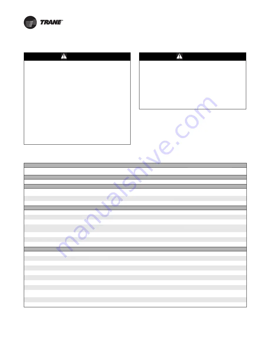
Maintenance Checklist

Table 18. Maintenance checklist

After 48 hours of operation

For belt-drive fans, the belts have acquired their permanent set. Readjust but do not overtighten. See 

“Tension the Fan Belt,” p. 62

 for more 

information.

Every week

Observe unit weekly for any change in running condition and unusual noise.

Every month

Clean or replace air filters if clogged or dirty; coat permanent filters with oil after cleaning; change bag filters when pressure drop is 1 in. wg. 
Se

“Air Filters,” p. 66

 for more information.

Belt-drive fans - re-lubricate fan bearings if necessary. See 

“Fan Bearing Lubrication,” p. 73

 for more information.

Belt-drive fans - check and adjust fan belt tension. Se

“Tension the Fan Belt,” p. 62

 for more information.

Every three to six months

Belt-drive fans - check fan bearing grease line connections. Lines should be tight to the bearings.

Check motor bracket torque. Se

Table 19, p. 72

 for torque requirements.

Belt-drive fans - check bearing bolt torque and bearing setscrew torque. Se

Table 19, p. 72

 for torque requirements.

Belt-drive fans - align fan and motor sheaves. Tighten sheave set screws to the proper torque. See 

“Align Fan and Motor Sheaves,” p. 64

 for 

more information.

Inspect and clean drain pans. See 

“Coils,” p. 66

 for more information.

Tighten electrical connections.

Inspect coils for dirt build-up. Se

“Coils,” p. 66

 for more information.

Every year 

Inspect the unit casing for corrosion. If damage is found, clean and repaint. 

Clean the fan wheels and shaft. See 

“Coils,” p. 66

 for more information.

Inspect and clean drain pans.

Check damper linkages, set screws, and blade adjustment. Clean, but do not lubricate, the nylon damper rod bushings.

Clean damper operators.

Inspect electrical components and insulation.

Inspect wiring for damage.

Rotate the fan wheel and check for obstructions. The wheel should not rub. Adjust the center if necessary.

Lubricate motor bearings in accordance with motor manufacturer’s recommendations (see 

“Motor Bearing Lubrication,” p. 73

 for more 

information).

Check condition of gasketing and insulation around unit, door and dampers.

Examine flex connections for cracks or leaks. Repair or replace damaged material.

Summary of Contents for Climate Changer UCCA

Page 1: ...30 SAFETY WARNING Only qualified personnel should install and service the equipment The installation starting up and servicing of heating ventilating and air conditioning equipment can be hazardous a...

Page 2: ...hazardous situation which if not avoided could result in minor or moderate injury It could also be used to alert against unsafe practices NOTICE Indicates a situation that could result in equipment o...

Page 3: ...ble electric heat voltage ratings in electrical requirements chapter Updated typical VFD wiring schematic for indoor and outdoor air handlers in the electrical requirements chapter Updated typical dua...

Page 4: ...ent and Assembly for Indoor Air Handlers 24 Unit Placement and Assembly for Outdoor Air Handlers 30 Duct Connections 35 Field Conversions 36 Coil Piping and Connections 38 General Recommendations 38 D...

Page 5: ...at identifies the type of section and functional components customer tagging information the unit serial number the unit order number the build section position for installation and the unit model num...

Page 6: ...are acceptable for ambient temperatures up to 104 F while motors with Class F insulation can withstand ambient temperatures to 140 F 60 C Note Units with UL approval have a maximum ambient temperature...

Page 7: ...for field provided controls Various end device options including Low limit protection Condensate overflow switch Fan status switch Filter status switch Discharge air sensor Mixed air sensor Return air...

Page 8: ...fpi T 8 row hydronic coil 14 fpi U 4 row DX coil 9 fpi V 4 row DX coil 12 fpi W 4 row DX coil 14 fpi Y 6 row DX coil 9 fpi Z 6 row DX coil 12 fpi 1 6 row DX coil 14 fpi S Special Digit 14 Unit Coil 2...

Page 9: ...fixed 850 950 variable G 950 rpm fixed 900 1000 variable H 1000 rpm fixed 950 1050 variable J 1050 rpm fixed 1000 1100 variable K 1100 rpm fixed 1050 1150 variable L 1150 rpm fixed 1100 1200 variable...

Page 10: ...at filter with back return single point power 8 2 in angle filter with back return single point power 9 2 in 4 in combination filter with back return single point power S Special Digit 29 Filter type...

Page 11: ...dlers and field installed accessories must be protected from the elements A controlled indoor environment is recommended for proper storage Note All factory shipping protection should be removed This...

Page 12: ...free air and necessary service access see Service Clearances p 14 Refer to submittals for specific minimums Allow room for supply and return piping ductwork electrical connections and coil removal Ens...

Page 13: ...al clearances 3 Remove any twist within the curb due to roof supports and square the curb 4 Level the curb 5 Secure the curb to the roof support members 6 Install 2 in thick boards or rigid insulation...

Page 14: ...66 00 66 00 C Fan Access return section motor side 48 00 48 00 48 00 51 00 54 00 58 00 61 00 61 00 66 00 66 00 D Control Box 56 00 56 00 56 00 56 00 56 00 56 00 56 00 56 00 56 00 56 00 E VFD 48 00 48...

Page 15: ...56 00 56 00 56 00 D Return Fan Door 48 00 48 00 48 00 51 00 54 00 58 00 61 00 61 00 66 00 66 00 E Filter mixing box economizer opposite coil connection side 30 00 34 00 32 00 32 00 30 00 35 00 35 00 3...

Page 16: ...8 70 78 70 80 20 84 30 84 30 87 00 93 60 Coils Hydronic DX coils galvanized and stainless steel casing Area ft2 2 80 5 60 7 60 9 90 12 30 14 30 16 30 20 40 24 00 28 50 Width in 17 50 22 50 27 50 27 50...

Page 17: ...6 90 8 90 11 10 16 30 16 30 20 00 22 50 26 40 30 60 Nominal Velocity fpm 432 0 432 0 450 0 450 0 369 2 430 8 425 0 466 7 473 7 490 9 2 in Angle Filter 16 x 20 2 6 6 6 4 12 16 x 25 2 3 3 8 20 x 20 4 2...

Page 18: ...46 164 44 125 00 161 00 241 00 160 00 17 133 09 172 89 160 00 256 00 241 00 125 00 21 155 81 290 14 196 00 n a 256 00 125 00 25 168 83 304 07 196 00 256 00 n a 250 00 30 208 34 317 00 250 00 322 00 n...

Page 19: ...00 15 20 15 22 00 27 230 V 60 Hz 3 PH 8 60 1800 15 20 15 22 00 27 460 V 60 Hz 3 PH 4 20 1800 4 80 12 11 00 20 575 V 60 Hz 3 PH 3 30 1800 3 90 20 9 00 25 5 200 V 60 Hz 3 PH 15 70 1800 22 00 22 42 00 31...

Page 20: ...FC Fan 3 10 1 Removescrewsattachingshippingprotectionbrackets from center of isolation base to casing mounting bracket 2 Remove shipping protection brackets through door Figure 5 Shipping tie down re...

Page 21: ...il ready to place the unit in its permanent location Figure 9 Shipping tie down removal for FC fan 12 30 Figure 10 Shipping tie down removal for DDP fan See Detail B Detail B See Detail C Detail C NOT...

Page 22: ...from the top of the unit WARNING Risk of Unit Dropping Failure to follow instruction below could result in death or serious injury To prevent modules subassemblies from dropping ALWAYS place assemble...

Page 23: ...should be used for larger units where forks cannot extend under both base rails Lifting Outdoor Units Note For outdoor air handlers preparation of the roof curb or pier mount and roof openings must be...

Page 24: ...lers If the air handler is ordered with a mixing box or angle filter section it will arrive in sections Some assembly may be required For details see Section assembly see Unit Assembly for Indoor Unit...

Page 25: ...frame can be mounted parallel to airflow or perpendicular to airflow WARNING Toxic Fumes Keep open flame away from unit exterior or interior Do not weld or use cutting torch on the exterior or interi...

Page 26: ...Base Frame If a factory provided integral base frame is used for ceiling suspension the individual sections and or subassemblies will have base frame shipping splits and base frame lifting lugs While...

Page 27: ...eld provided wiring Consider overall unit serviceability and accessibility before mounting running wires power making cabinet penetrations or mounting any components to the cabinet Joining at Shipping...

Page 28: ...o a tight space the second level fan section of a vertical unit can be removed to maneuver the unit into the space Removal will require field supplied lifting lugs part LUG00180 1 Remove screws Item 2...

Page 29: ...a control interface VFD or electric heat disconnect electrical wiring Wiring between fan motor and contactor or VFD can be disconnected via quick connects in the control interface or VFD box respecti...

Page 30: ...perimeter of the unit Both the unit and the pipe cabinet should be supported by their base channel around the entire perimeter see Figure 32 and Figure 33 Assembly If a unit arrives in sections then e...

Page 31: ...ack of pipe cabinet side wall full height of the side wall along the outer edge to base and roof full length of the roof along the outer edge and peel off the liner Strips of tape must contact each ot...

Page 32: ...rews mount the weather hoods to the unit 4 Units withmultiple intakehoodsrequire that the hoods be installed from bottom to top Overlap locations should be sealed with butyl caulk between the hoods No...

Page 33: ...Installation Mechanical CLCH SVX009J EN 33 Figure 36 Intake hood installation Butyl caulk tape 1 00W x 0 125T Butyl caulk tape 1 00W x 0 125T Screw self drille 0 250 14 x 0 7 Intake hoods...

Page 34: ...5 20 25 20 20 20 20 25 16 25 16 20 16 20 16 Size 25 26 40 ft 20 25 20 25 20 25 20 25 20 25 20 25 25 16 25 16 Size 30 30 60 ft 20 25 20 25 20 25 20 25 25 16 25 16 25 16 25 16 25 16 25 16 Size 17 20 00...

Page 35: ...back up into the drain pan causing it to overflow See Drain Pan Trapping p 38 Fan Discharge Connections To ensure the highest fan efficiency duct turns and transitions must be made carefully minimizin...

Page 36: ...hat secure the coil to the cabinet roof Remove the screws that attach the roof to the side walls and the front panel 4 Remove roof 5 If horizontal front or back discharge loosen and remove j bolt secu...

Page 37: ...djust the isolators to achieve the proper operation height of the fan and motor isolation base Minimum required clearances are listed in Table 7 To determine the isolator clearances on all unit sizes...

Page 38: ...ain pan for cleaning purposes only it does not need a trap however a cap or shutoff valve should be installed on the drain connection Only sections handling condensate such as a cooling coil section o...

Page 39: ...egative pressure L H J pipe diameter where H 1 inch for each inch of negative pressure plus 1 inch J 1 2 H Section under positive pressure L H J pipe diameter where H 1 2 inch minimum J 1 2 inch plus...

Page 40: ...de of the trap 4 If installing coils in series airflow control each coil bank independently with an automatic steam control valve Size the traps for each coil using the capacity of the first coil in d...

Page 41: ...ty is below these minimums vent the coil by one of the following methods 1 Install an air vent in the top pipe plug tapping of the return header 2 When the return line rises above the top of the coil...

Page 42: ...tailed schematics of evaporator piping Figure 49 Example of placement for split system components Discharge line Manual ball valve Access port Filter Access port Access port Filter drier with access p...

Page 43: ...t systems with mircochannel heat exchanger condensers MCHE solenoid valves isolate the refrigerant from the evaporator during the off cycles Trim solenoids cannot be used with MCHE Note Trane condensi...

Page 44: ...installed after the system is cleaned up Access port The access port is used to determine suction pressure This port is usually a Schraeder valve with a core Frostat coil frost protection The Frostat...

Page 45: ...suitable for use with R 410A These same lines sized at 1 5 8 OD or 2 1 8 OD must use type K or thicker wall Expansion valves need to be reselected Expansion valves are refrigerant specific Any gasket...

Page 46: ...ader connection 4 Use the tube diameter recommended in the condensing unit application manual for a vertical rise Ensure that the top of the riser is higher than the evaporator coil 5 Pitch the suctio...

Page 47: ...Use the tube diameter recommended for a vertical rise as specified in the condensing unit application manual Assure the top of the riser is higher than the evaporator coil 7 Pitch the suction line sl...

Page 48: ...meter recommended for a vertical rise as specified in the condensing unit application manual Ensure that the top of the riser is higher than the evaporator coil 7 Pitch the suction line slightly 1 in...

Page 49: ...a vertical rise as specified in the condensing unit application manual 5 The top of the Circuit 2 suction riser must be higher than the top evaporator coil Use the tube diameter recommended for a vert...

Page 50: ...as specified in the condensing unit application manual Ensure that the top of the riser is higher than the evaporator coil 7 Pitch the suction line slightly 1 in 10 feet so that the refrigerant drains...

Page 51: ...circuit Ground loops can affect the measurement accuracy of the controller Allinput output circuits except isolated relay contacts and optically isolated inputs assume a grounded source either a groun...

Page 52: ...ents Line voltage 24 Vac Transformer Termination board Table 11 Electric heat voltage ratings Unit Voltage Heater Voltage 200 200 230 230 460 460 575 575 Table 12 Electric heat kW limits min max Motor...

Page 53: ...COPIED OR ITS CONTENTS DISCLOSED TO OUTSIDE PARTIES WITHOUT THE WRITTEN CONSENT OF TRANE DRAWN BY DATE DO NOT SCALE PRINT X XX XXX THIRD ANGLE PROJECTION c B B B UNLESS OTHERWISE SPECIFIED ALL DIMENSI...

Page 54: ...ITTEN CONSENT OF TRANE DRAWN BY DATE DO NOT SCALE PRINT X XX XXX THIRD ANGLE PROJECTION c B B B UNLESS OTHERWISE SPECIFIED ALL DIMENSIONS ARE IN INCHES TOLERANCE ANGLES B HOLE DIA CONFORMS TO ASME Y14...

Page 55: ...TTEN CONSENT OF TRANE DRAWN BY DATE DO NOT SCALE PRINT X XX XXX THIRD ANGLE PROJECTION c B B B UNLESS OTHERWISE SPECIFIED ALL DIMENSIONS ARE IN INCHES TOLERANCE ANGLES B HOLE DIA CONFORMS TO ASME Y14...

Page 56: ...WRITTEN CONSENT OF TRANE DRAWN BY DATE DO NOT SCALE PRINT X XX XXX THIRD ANGLE PROJECTION c B B B UNLESS OTHERWISE SPECIFIED ALL DIMENSIONS ARE IN INCHES TOLERANCE ANGLES B HOLE DIA CONFORMS TO ASME Y...

Page 57: ...N CONSENT OF TRANE DRAWN BY DATE DO NOT SCALE PRINT X XX XXX THIRD ANGLE PROJECTION c B B B UNLESS OTHERWISE SPECIFIED ALL DIMENSIONS ARE IN INCHES TOLERANCE ANGLES B HOLE DIA CONFORMS TO ASME Y14 5M...

Page 58: ...WRITTEN CONSENT OF TRANE DRAWN BY DATE DO NOT SCALE PRINT X XX XXX THIRD ANGLE PROJECTION c B B B UNLESS OTHERWISE SPECIFIED ALL DIMENSIONS ARE IN INCHES TOLERANCE ANGLES B HOLE DIA CONFORMS TO ASME...

Page 59: ...brication if necessary See Fan Bearing Lubrication p 73 Coil Related Checks Ensure coil and condensate drain piping connections are complete Check the piping and valves for leaks Open or close the val...

Page 60: ...ltage imbalance is 2 percent Voltage imbalance is defined as 100 times the sum of the deviation of the three voltages from the average divided by twice the average voltage For example if the three mea...

Page 61: ...plate 1 22 Motor Voltage Depends on unit Set Based on Motor Nameplate 1 24 Motor Current Depends on unit Set Based on Motor Nameplate 1 25 Rated Motor Speed Depends on unit Set Based on Motor Nameplat...

Page 62: ...5 Determine actual deflection by depressing one belt with the belt tensiometer and measuring the deflection relative to the other belts or to belt line see Figure 66 Adjust the belt tension to the cor...

Page 63: ...4 8 5 12 6 2 501 4 000 6 0 8 9 7 3 10 9 C CX 7 0 9 0 500 1 740 11 5 17 0 14 7 21 8 1 741 3 000 9 4 13 8 11 9 17 5 9 5 16 0 500 1 740 14 1 21 0 15 9 23 5 1 741 3 000 12 5 18 5 14 6 21 6 D 12 0 16 0 200...

Page 64: ...as required After realignment tighten the belts again to the standard belt tensioning specifications If the force is still not the same for all belts the belts or sheaves are worn and must be replaced...

Page 65: ...e in running condition and unusual noise Every month Clean or replace air filters if clogged or dirty coat permanent filters with oil after cleaning change bag filters when pressure drop is 1 in wg Se...

Page 66: ...electric power including remote disconnects before servicing Follow proper lockout tagout procedures to ensure the power can not be inadvertently energized Secure rotor to ensure rotor cannot freewhe...

Page 67: ...angle of 15 degrees Spray perpendicular to the coil face Keep the nozzle at least 6 inches from the coil Do not exceed 600 psi 7 Spray the leaving air side of the coil first then the entering air sid...

Page 68: ...ystem during startup If draining is questionable because of dirt or scale deposits inside the coil fill the coil with glycol before the heating season begins Note On many unit sizes there are multiple...

Page 69: ...bleach and water solution or an EPA approved sanitizer specifically designed for HVAC use 6 Immediately rinse the affected surfaces thoroughly with fresh water and a fresh sponge to prevent potential...

Page 70: ...orized impeller fan access through coil door Horizontal units equipped with a direct drive plenum fan the low limit switch can be accessed through the fan access door For sizes 3 6 10 and 12 see Figur...

Page 71: ...Removable access panel Screw 10 16 x 0 750 self driller Remove all from perimeter panel Panel removed from unit Low limit freeze stat Detail A Figure 75 Resetting low limit switch for horizontal DDP...

Page 72: ...ated materials and cleaning solution Bearing Set Screw Alignment Align bearing set screws for belt drive fans as illustrated in Figure 76 See Table 17 p 64 for set screw torque measurements Torque Req...

Page 73: ...tions so please obtain the motor IOM and use the manufacturer recommended grease Fan Motor Inspection Inspect fan motors periodically for excessive vibration or temperature Operating conditions will v...

Page 74: ...wer company for adjustments Mechanical failure Check that motor and drive rotate freely Check bearing lubricant Motor stalls Open phase Check line for an open phase Overloaded motor Reduce load or rep...

Page 75: ...ce see Coils p 66 Do not use steam to clean refrigerant coils Fin frosting Verify defrost cycle operation Verify frostat operation Verify refrigerant charge Low steam coil capacity Incorrect airflow C...

Page 76: ...re committed to using environmentally conscious print practices Trane by Trane Technologies NYSE TT a global climate innovator creates comfortable energy efficient indoor environments for commercial a...

Reviews: