10 |
P a g e
2) Wiring Connections
Once the LINK is installed, the control wires will be available inside the junction box the LINK
is connected to. The wiring diagram in section A.2 is also applicable here. You can control the
dispenser solenoid valve, dispenser motor, dispenser control signal input or other such device.
The installation typically involves disconnecting the AC power source, making the appropriate
electrical connections and re-connecting the wires to the FluidSecure LINK and dispenser.
Under no condition should a FluidSecure LINK control a pump motor larger than
3/4hp.
Larger loads can be controlled with an external contactor or power relay.
3) Pulser Installation
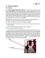
Many dispensers have included pulsers which can be attached to the FluidSecure
LINK. To connect to an existing pulser wire that is
located outside the conduit system
,
you must utilize the cable and connector that is supplied with the FluidSecure LINK. The
external pulser wiring from the FluidSecure LINK is designed intrinsically safe and can
be safely run without conduit in a Class 1, Division 1 location or any lesser classification.
Do NOT allow it to enter into a junction box, conduit or other device that could connect
these pulser wires to external high voltage wiring
Other pulsers often have their pulser wires
within the conduit system
and can
connect to the internal LINK pulser wires. Those pulser wires are shown in the drawing
in section A.2 and are labeled orange and gray. The gray wire is ground and the orange
wire is positive DC.
It is not within the scope of this document to cover all possible pulser combinations
that exist on standard dispensers. However, there are generally two common types that
are often used.
1. Reed Switch or microswitch - This is a non- powered switch that opens and closes
for every tenth of a gallon. Some will count more often and others less but a 1/10-gallon
pulse rate is extremely common in the commercial environment. Connect either wire from
this type pulser to the red and green wire in the pulser cable.
2. Open Collector - This is a powered pulser and generally requires 5 to 12 volts to
operate. In general, you will have to determine which of the pulsers wires is ground and
which are the pulse output. Additionally, if the pulser requires external excitation, you
may have to connect a 5 or 12-volt line to the pulser. The FluidSecure LINK produces a
5 VDC output that can be used to power an open collector circuit. The diagram in section
A.2 shows those connections.


