background image


User's Guide  l  MBox-Advanced UG 0101  l  © 2019, TQ-Systems GmbH 


Page  7 


4.3.1.1


Power Supply Connector 

The MBox-Advanced has a wide-range voltage input of 9 V to 36 V DC. 


Connector type: Phoenix MC 1,5/ 2-GF-3,5-LR (1817615) 


Mating connector: e.g. Phoenix FMC 1,5/ 2-STF-3,5


(1966091) 


Table 2: 

Pinout Power-In Connector 

Pin 

Signal 

Remark 

1 (+) 

9 to 36 V 

Fused @ 5A 

2 (–) 

GND 

– 


Illustration 3: 

DC Power Supply Connector 


Note: MBox-Advanced applying power 


Do not connect or disconnect the power supply of the MBox-Advanced under voltage. 
Switch off the voltage before unplugging. 


4.3.1.2


USB Host Interfaces 

The MBox-Advanced provides two USB 3.0 and one USB2.0 host interface. 
USB cables connected at these interfaces should have a maximum length of 3 meter. 


4.3.1.3


Gigabit Ethernet 

The MBox-Advanced provides four Gigabit Ethernet ports. 
Ethernet controllers with 10/100/1000 Mbps speed are implemented on both ports. 
 

Table 3: 

Ethernet LEDs 


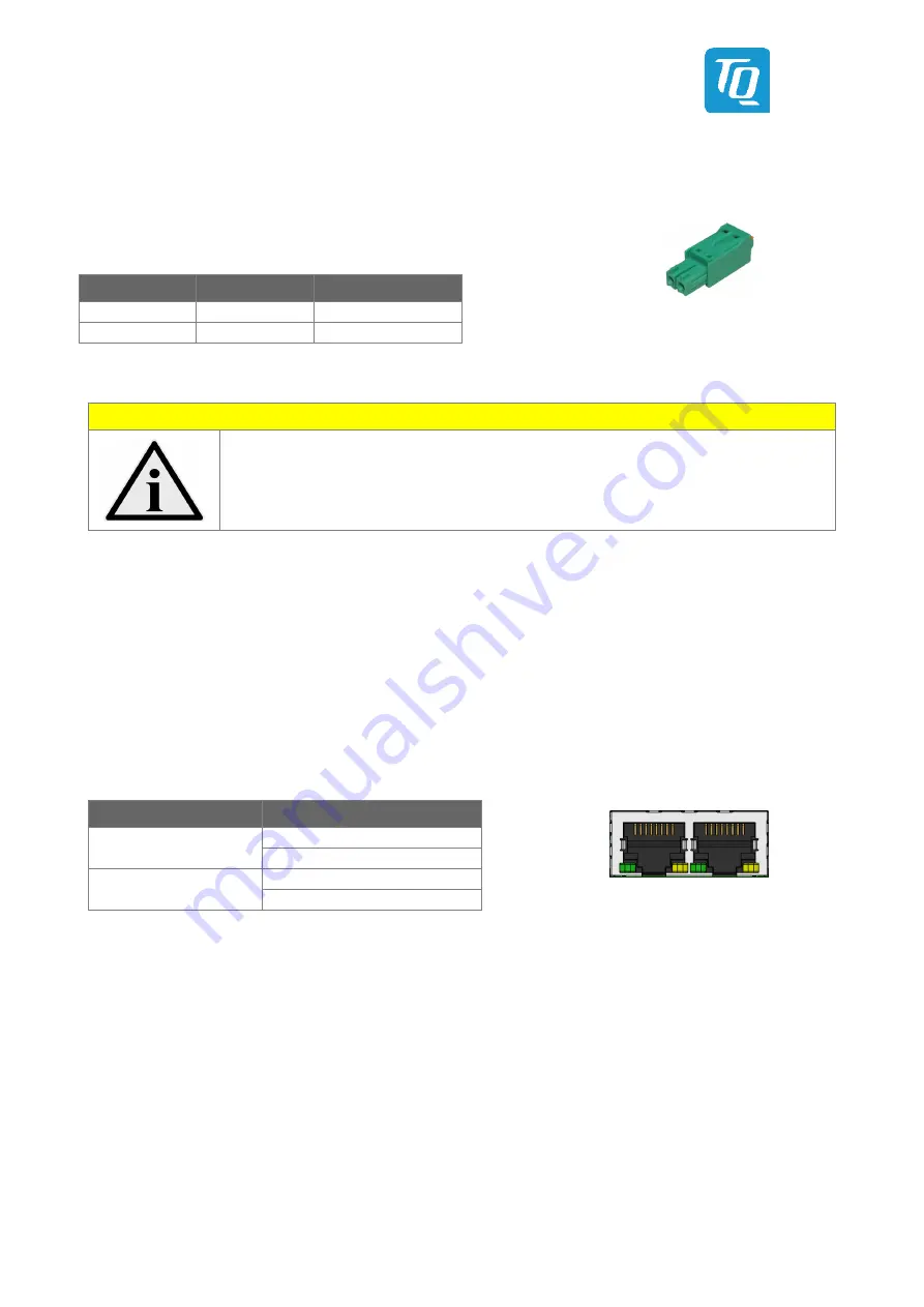
Illustration 4: 

RJ45 Connectors 


4.3.1.4


RS-232 Serial Interface 

The MBox-Advanced provides one serial port: 


D-Sub RS-232 port (4-wire) 


Legacy compatible (IO addresses and IRQs) 


Up to 115 kbaud 


4.3.1.5


DisplayPort 

The MBox-Advanced provides one DisplayPort interface, which supports DP++ signalling. 
Thus monitors with DP, DVI, HDMI and VGA input can be connected using dedicated cables and adapters. 
 

LED 

Status 

Left, green (Link) 

Off: no link 
LED is lit: link established 

Right, yellow (ACT) 

Off: no activity 
LED is lit: activity 

– 

Summary of Contents for MBox-Advanced

Page 1: ...User s Guide l MBox Advanced UG 0101 l 2019 TQ Systems GmbH Page i MBox Advanced User s Guide MBox Advanced UG 0101 2019 12 04...

Page 2: ...5 4 1 2 Power Consumption 5 4 2 Environmental Conditions 5 4 3 Connectors and Interfaces 6 4 3 1 External Connectors 6 4 3 1 1 Power Supply Connector 7 4 3 1 2 USB Host Interfaces 7 4 3 1 3 Gigabit Et...

Page 3: ...Box Advanced Mounting 1 11 Illustration 9 MBox Advanced Mounting 2 11 Illustration 10 MBox Advanced Mounting 3 11 Illustration 11 SATA Mounting 1 12 Illustration 12 SATA Mounting 2 12 Illustration 13...

Page 4: ...it before you start working with the MBox Advanced This User s Guide provides information which is essential for proper operation of the MBox Advanced General safety instructions must be adhered to an...

Page 5: ...n helps you to safely use the MBox Advanced Follow and keep all information provided with the MBox Advanced The information in this User s Guide does not alter the terms of your purchase agreement or...

Page 6: ...ne should conclude that brand and trademarks are rightly protected by a third party 2 3 Disclaimer TQ Systems GmbH does not guarantee that the information in this User s Guide is up to date correct co...

Page 7: ...ng key functions are implemented in the MBox Advanced External Interfaces standard 4 Gigabit Ethernet 2 USB 3 0 1 RS 232 Power button Reset button Internal Interfaces and connection possibilities M 2...

Page 8: ...e maximum power consumption of all components must be taken into account 4 2 Environmental Conditions The following temperature parameters were determined by qualification tests standard configuration...

Page 9: ...ms GmbH Page 6 4 3 Connectors and Interfaces 4 3 1 External Connectors Illustration 1 MBox Advanced Front View Illustration 2 MBox Advanced Rear View 4 Ethernet RS 232 2 USB 3 0 Power button Reset but...

Page 10: ...SB 3 0 and one USB2 0 host interface USB cables connected at these interfaces should have a maximum length of 3 meter 4 3 1 3 Gigabit Ethernet The MBox Advanced provides four Gigabit Ethernet ports Et...

Page 11: ...ble at the front Table 5 Power LED Table 6 General Purpose LED 4 3 2 Optional External Connectors and Interfaces 4 3 2 1 M 2 Socket with B Key for I O devices The MBox Advanced provides an M 2 socket...

Page 12: ...0101 l 2019 TQ Systems GmbH Page 9 5 MECHANICS 5 1 Dimensions The following illustrations show the MBox Advanced All dimensions are in mm Illustration 5 MBox Advanced Dimensions Front Illustration 6...

Page 13: ...chapter Accessories 3 4 for more information Adapter plate Please see chapter Accessories 3 4 for more information Directly with screws The housing provides six M4 threads for various mounting options...

Page 14: ...anced remove two screws at the sides Illustration 8 MBox Advanced Mounting 1 2 Pull off the rear panel Illustration 9 MBox Advanced Mounting 2 3 Turn the bottom plate 45 and then pulled it off Illustr...

Page 15: ...1 Open the housing as described in chapter 5 3 2 Remove the left two screws and open the right two screws Illustration 11 SATA Mounting 1 3 Push the mounting frame in the direction of the red arrow I...

Page 16: ...storage in the mounting frame The SATA connector points in the direction of the indicator arrow Illustration 13 SATA Mounting 3 2 Fasten the mass storage to the mounting frame with four screws M3 5 I...

Page 17: ...the mass storage in the system and align it with the two screws Illustration 16 SATA Mounting 6 5 Slide the mounting frame in the direction of the arrow until the mounting lugs slide under the screw...

Page 18: ...part 15 of the FCC Rules These limits are designed to provide reasonable protection against harmful interference in a residential installation This equipment generates uses and can radiate radio frequ...

Page 19: ...ughout the European Union 7 2 Recycling Users of the MBox Advanced must not dispose the MBox Advanced as unsorted municipal waste but use the collection framework available in their country for the re...

Page 20: ...TQ Systems GmbH M hlstra e 2 l Gut Delling l 82229 Seefeld info tq group com l www tq group com...

Reviews: