TOYOTA 4RUNNER
2020 –
DASH CAMERA
PROCEDURE
Page 16 of 24
Issue D: 11/06/19
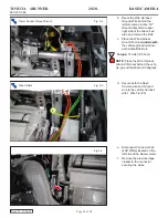
j.
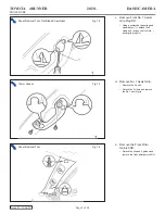
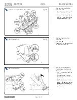
Route the Wire Harness with
T-taps to the Connector F42.
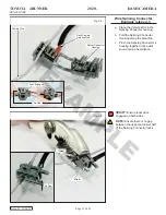
NOTE:
Reference steps g-i for
Wire Splicing Connector example.
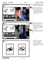
k.
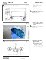
Install the Wire Harness
with the Red Wire Splicing
Connector to the BLUE wire
on Pin# 1 of Connector F42
(40P, White).
Pliers
Fig. 3-7
Pliers
Fig. 3-8
Pliers
Fig. 3-9
20 19 18 17 16 15 14 13 12 11 10 9 8 7
4
2 1
3
24
25
26
27
28
29
30
31
32
33
34
35
36
37
38
39
40
22
23
21
5
6
20 19 18 17 16 15 14 13 12 11 10 9 8 7
4
2 1
3
24
25
26
27
28
29
30
31
32
33
34
35
36
37
38
39
40
22
23
21
5
6
Connector View from Wire Side
Connector View from Wire Side
Splicing Connector
Splicing Connector
Hinges
Hinges
Pliers
Pliers
Blue Wire
Violet Wire
Splicing Connector
Foam Tape (30x80mm)
Foam Tape (63x80mm)
Fuse
NOTE:
Reference steps g-i for
Wire Splicing Connector example.
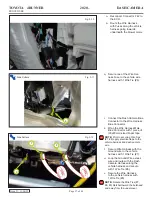
l.
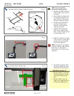
Install the Wire Harness
with the Yellow Wire Splicing
Connector to the VIOLET wire
on Pin# 21 of Connector FN1
(40P, White).
NOTE:
Stagger the T-tap connec-
tions (do not place T-taps side by
side).
m.
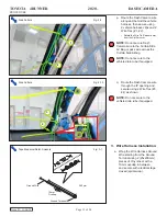
Wrap the 2 Wire Harness
Fuse using 2 (63x80mm)
pieces of Foam tape.
n.
Wrap the Splicing connectors
using 2 (30x80mm) pieces of
Foam tape.

