SAFETY MECHANISM
1. Overflow Prevention
(a) If the lifter is tilted while in operation, the red lamp comes on and the operation
stops.
(b) If an electric part is in malfunction and the oil level exceeds the normal oil level,
the red lamp comes on and the operation stops.
2. Idle Operation Prevention
If the fuel sump is empty while in operation or if the lifter does not pump up the fuel
because of a pump malfunction, etc.,for more than 20 minutes the yellow lamp comes
on and the motor stops.
3. Continuous Operation Prevention
If the lifter is operated over for 30 minutes due to motor lock, all lamps will flash and the
operation is stopped.
OPERATION
■
When Operating Lifter For The First Time After Installation:
Before operating the lifter in the following procedure, check if installation and piping are
performed in the manner as described in "INSTALLATION" (Page 11~13) and "PIPING" (Page 15~17).
1. Remove the cover screw at the upper side of the cover and remove the cover
bringing it slightly forward.
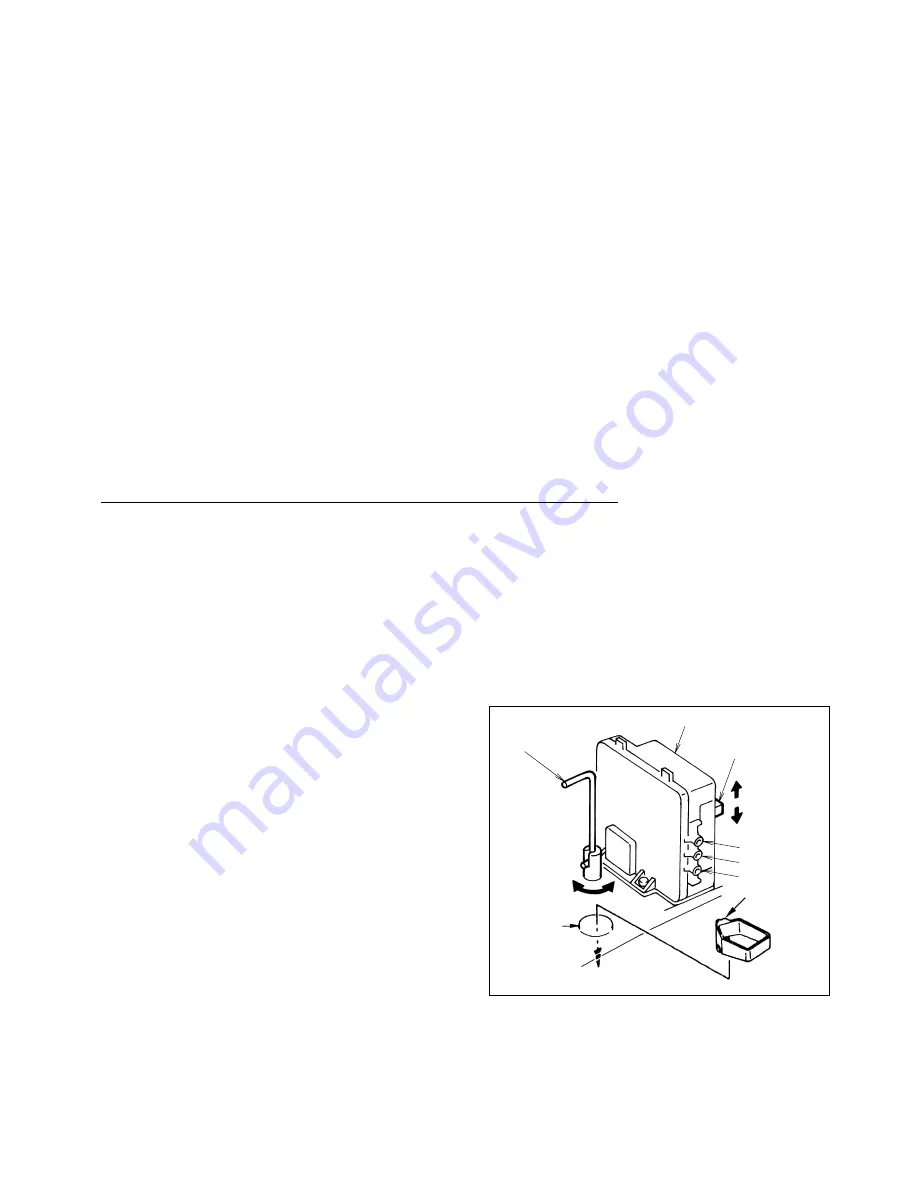
2. Set the outlet valve lever to CLOSE by pulling up and rotating the lever, turn the operation
switch to OFF position (Fig. 3), and put the power supply cord into the electrical outlet. The
yellow lamp will flash to indicate insufficient oil in the fuel sump.
3. Pour about 0.12 gallons (450 cc) of fuel into
the fuel opening by using the attached funnel.
When the fuel sump is filled sufficiently, the green
lamp will flash to indicate the normal oil level. (Fig. 3)
CAUTION: Use clear or red colored kerosene or
No.1 or No.2 Fuel Oil only!
Be sure there is no contamination
such as dirt, water or other particles.
Note: If an excessive amount of fuel is filled,
the red lamp will flash to indicate excessive
oil level. In this case, set the outlet valve
lever to OPEN and supply fuel to the heater
until it reaches normal oil level. (Fig. 3)
6
4. Turn the operation switch to ON position. The green lamp will change from flashing to continuous
and the motor will start operating.
CAUTION: Do not touch the motor fan. The motor fan will start at the same time
when turning the operation switch to ON position.
Red lamp
Green lamp
Yellow lamp
Outlet valve
lever
Control box
OPERATION
switch
CLOSE
OPEN
Fig. 3
ON
OFF
Fuel opening
with rubber cap
Put the funnel
into the opening
Funnel


