

39
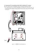
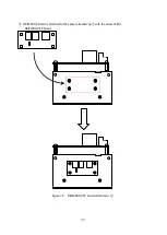
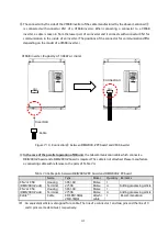
The connector by the side of 5 pins of an attached cable is connected with connector CN1 of a
DBIF2009-Z board.
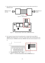
Figure 7.6 Attached cable
IF
-Z
W
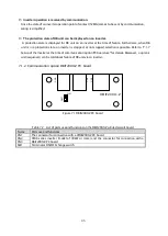
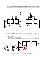
Figure 7.7
Connection between attached cable and DBIF2009-Z board
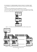
The connector by the side of 6 pins of an attached cable is connected with connector CN6 of a
VFDB2009-Z board. When DB unit is connected in parallel, please make connection between each
attached cable, and a DBIF2009-Z board and a VFDB2009-Z board like the above-mentioned
and
.
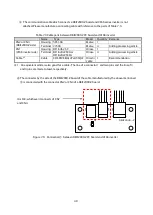
Figure 7.8
Connection between attached cable and VFDB2009-Z board
VFDB2009-Z board
side (CN6)
DBIF2009-Z board
side (CN1)
Intact pin
Summary of Contents for VFDB2009 Series
Page 1: ...VFDB2009 Operation Manual...


