
16
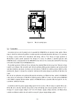
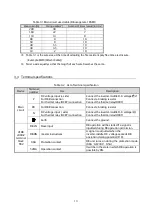
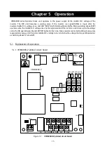
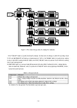
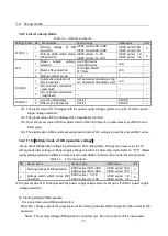
Table 5.1 List of parts use and functions on the VFDB2009-Z printed cuicuit board
Name
※
5
Parts use and functions
CN2
The connector for a change of a power supply voltage system
CN3
CN6
The connector for connection with communication option DBIF2009-Z PC board
(
※
1
)
LED8
LED for a normal operation check of CPU
(
※
2
)
LED9
CHG lamp
(
※
3
)
TB2
The terminal block for DB unit control
(
※
4
)
※
1:
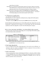
Refer to "7.1 communication option DBIF2009-Z PC board" for a communication option board.
※
2:
LED8 blinks in a cycle of about 2 seconds, while the VFDB2009-Z board is operating normally. While not
blinking, failure of the loose connection of CN1 or a VFDB2009-Z board can be considered.
※
3:
The middle D.C. voltage of an inverter turns on LED9 by 30V or more. When the light is not switched on,
failure of the loose connection of CN1 or a VFDB2009-Z board can be considered.
※
4:
Refer to "3.3 Terminal specifications" for the function of TB2.
※
5:
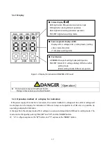
Refer to "5.1.2 Display" for LED 1-7 and SW 1-3.
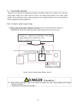
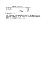
DANGER
[
VFDB2009-Z
PC board
]
DB unit cannot be recklessly touched during CHG LED lighting.
Failure to do so may cause electric shock.
Wiring of TB1,CN1,CN4,CN5 are not changed.
Failure to do so may cause electric shock or personal injury and part breakage
Summary of Contents for VFDB2009 Series
Page 1: ...VFDB2009 Operation Manual...


