

15
Chapter 5 Operation
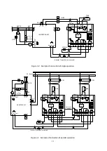
VFDB2009 series Dynamic brake unit operates in the power supply of the middle D.C. voltage of the
inverter. The DB unit becomes a waiting state if the inverter run signal(52MA) is input after the
inverter-
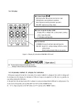
middle D.C. voltage rises, and LED “RUN"
(Light Emitting Diode) lights. Main switching device(IGBT)
operates when the middle D.C. voltage rises by the regeneration of the inverter, and it rises up to the voltage
set to the DB operating point,and LED
“DB" lights.
At this time, brake resistor connected to DB unit consumes
regeneration energy, and if inverter-middle D.C. voltage turns into below the voltage that stops DB operation,
a switching device is turned off.
5.1
Explanation of operation
5.1.1
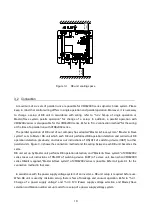
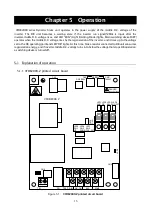
VFDB2009-Z printed circuit board
Figure 5.1
VFDB2009-Z printed circuit board
TB2 DB-IN DB-ON
86A
52MA
CN1
CN
CN
CN4
CN5 [200V]
[400V]
DB
電圧
CN6
LED1 LED2 LED3
RUN
LED
8
LED
9
C
H
G
LED4
DB 86A FNC/SET
VFDB2009-Z
TB1
LED5 LED6 LED7
SW1 SW2 SW3
UP
DOWN FNC/SET
DANGER
Hazardous Voltage
RY1
Summary of Contents for VFDB2009 Series
Page 1: ...VFDB2009 Operation Manual...


