background image

DS4-2731C 

- 20 -


13. Revision history 


Date 

Contents of revision 

Remarks 

2010.03.31 

Newly issued 

Development 1

2010.04.09 

CC-Link version added 

Development 1

2010.07.26 

Editorial errors with addresses in 12 “Contact” corrected 

Development 1

  2011.04.22 
 

Page 1, CE mark added. 
Page 13, 6-4-4. Measures to be taken to comply with the 

EMC Directive, added. 

Page 19, Department names changed due to change of 

organization in 12. Contact. 

Development 1


Blank 


Summary of Contents for SOT-MQ162 Series

Page 1: ...DS4 2731C 1 CC Link Space Optical Repeater SOT MQ82 162 series Operation Manual TOYO ELECTRIC CORPORATION...

Page 2: ...ts and their functions 5 6 Data linking procedure 6 6 1 Procedure 6 6 2 Setting the switches 7 6 3 Installation 8 6 4 Electric connections 11 6 5 Beam path adjustment 14 6 6 Monitoring function 14 7 E...

Page 3: ...d 4 Dip switch allows to switch the channel to the one having different carrier frequency and to communicate with up to two opposite directions in series or parallel without interference 3 Constructio...

Page 4: ...uts CDO On when data is received ALM Off when the reception level is low A photo coupler insulated NPN open collector output Rated output level 30VDC 50mA max Electric connections For CC Link signals...

Page 5: ...a from cable indicator RD1 Shows green when data is received from the cable 10 Received from optical unit indicator RD2 Shows green when data is received from the optical unit 11 Channel indicator CH...

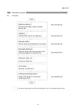
Page 6: ...and dedicated CC Link cables See subsection 6 4 Beam path adjustment Adjust the beam path while checking the CD and level indicators on each SOT unit See subsection 6 5 Setting the master unit Set up...

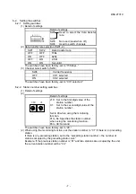
Page 7: ...es 1 Detail of settings 2 Detail of settings 10 1 x10 Set to the first digit value of the station number X1 Set to the second digit value of the station number Set to 00 when using the monitoring func...

Page 8: ...e rating 4 a device generating a strong magnetic field e g magnet or motor or a device or power wire generating strong noises e g inverter is used nearby 5 the sunlight or incandescent light containin...

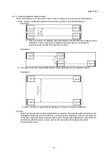
Page 9: ...2 This setup does not cause interferences unless disturbed by any reflective object Example 3 3 Same condition is applicable as Example 1 when the channel is different Caution Note that the severity o...

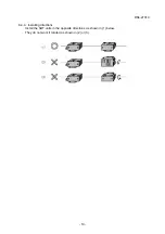
Page 10: ...DS4 2731C 10 6 3 4 Installing directions Install the SOT units in the opposite directions as shown in 1 below They do not work if rotated as shown in 2 or 3...

Page 11: ...ge drop across the cable and use it within a length not exceeding 50m 6 4 2 Signal connector Signal name Code Terminal number Signal A DA 1 Signal B DB 2 Signal ground DG 3 Shielded SLD 4 Arrangement...

Page 12: ...ee the User s Manual for the master unit 3 For the units at either ends of each segment always connect the terminal resistor between DA and DB The SOT units themselves contain no terminal resistor Use...

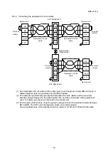
Page 13: ...he CC Link cable in the vicinity of the optical transmission device This ferrite core must have attenuation characteristics equivalent to those of the TDK ZCAT3035 1330 ferrite core Please note that t...

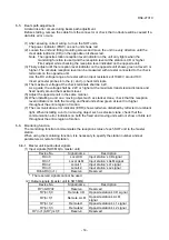
Page 14: ...opposite unit in the same manner 6 When installing a unit on a moving object such as stacker crane check that the reception level indicators on both the moving and fixed units show green at level 3 or...

Page 15: ...the station number of SOT MS162A to 1 and that of SOT MS162B to 2 3 Program the automatic refreshing RX refreshing device X1000 RY refreshing device Y1000 4 Set parameters Station type Remote I O of o...

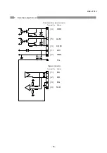
Page 16: ...DS4 2731C 16 7 External output circuit 1 DA 2 DB 3 DG 4 SLD 4 Terminal No Abbrev CDO 5 ALM 2 GND FG 1 24V 3 COM Signal connector Power auxiliary output connector Terminal No Abbrev...

Page 17: ...set Data cannot be transmitted for about two seconds after power up 3 Beam path adjustment When installing the SOT units never fail to adjust the beam path Data can be transmitted when the clear data...

Page 18: ...DS4 2731C 18 10 External dimensions As removed from bracket 5 x 12 oblong hole Receiver port Projector port 5 x 12 oblong hole...

Page 19: ...a failure of the product 12 Contact For detail of the product please contact the nearest sales office or the Kagiya Factory TOYO ELECTRIC CORPORATION Kagiya Factory Head office Kagiya Factory 1 39 Az...

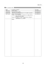
Page 20: ...Link version added Development 1 2010 07 26 Editorial errors with addresses in 12 Contact corrected Development 1 2011 04 22 Page 1 CE mark added Page 13 6 4 4 Measures to be taken to comply with the...

Reviews: