DS4-2731C
- 15 -
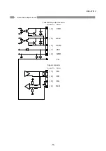
* The reserved signals cannot be used.
6-6-2. Correspondence between input/output signals and indicators
The correspondence between the input/output signal on/off statuses and the indicator
statuses is shown below:
Signal Indicator
LEVEL
CD ALM L1
L2 CD 1 2 3 4
OFF
OFF
OFF OFF
× × × × ×
ON OFF OFF OFF
{
× × × ×
ON ON OFF OFF
{
{
× × ×
ON ON ON OFF
{
{
{
× ×
ON ON OFF ON
{
{
{
{
×
ON ON ON ON
{
{
{
{
{
6-6-3. Example of program
(1) Example of system construction
In this example, the QCPU, QJ61BT11N and SOT-MS are set up as shown below for explanation.
1. Insert the QJ61BT11N into slot 0.
2. Set the station number of SOT-MS162A
to “1” and that of SOT-MS162B to “2.”
3. Program the automatic refreshing.
RX refreshing device: X1000
RY refreshing device: Y1000
4. Set parameters
Station type: Remote I/O
# of occupied stations: 1
* For detail of parameter settings, see
the User’s Manual for the master unit.
(2) Monitoring program
With this monitoring program, the reception level at the opposite station can be determined with
the indicator and used for fine adjustment and maintenance.
× : Off
{
: On
Slot 0
Power un
it
162A, station
number “1”
162B, station
number “2”
Send reception level at
station 1 to station 2
Send reception level at
station 2 to station 1
Reception level at station 1
decreased when M0 is off
Reception level at station 2
decreased when M1 is off

