


7
❏
5. With the servos centered, check to make sure that the
control surfaces are centered. If they need to be adjusted,
loosen the locking screw on the pushrod connector and
adjust the fl ight control until it is centered. When you are
satisfi ed, tighten the locking screw to hold the pushrod wires
in position. For added security, we recommend removing the
locking screws, applying a drop of thread locking compound
to the threads and re-installing the locking screws.
❏
6. Using your radio, center the aileron servos. Check to see
that the ailerons are also centered. If they need adjustment,
loosen the locking screw and adjust the ailerons until they
are centered at zero defl ection. Tighten the set screw of the
screw lock pushrod connector. Again, use threadlocker on
the threads.
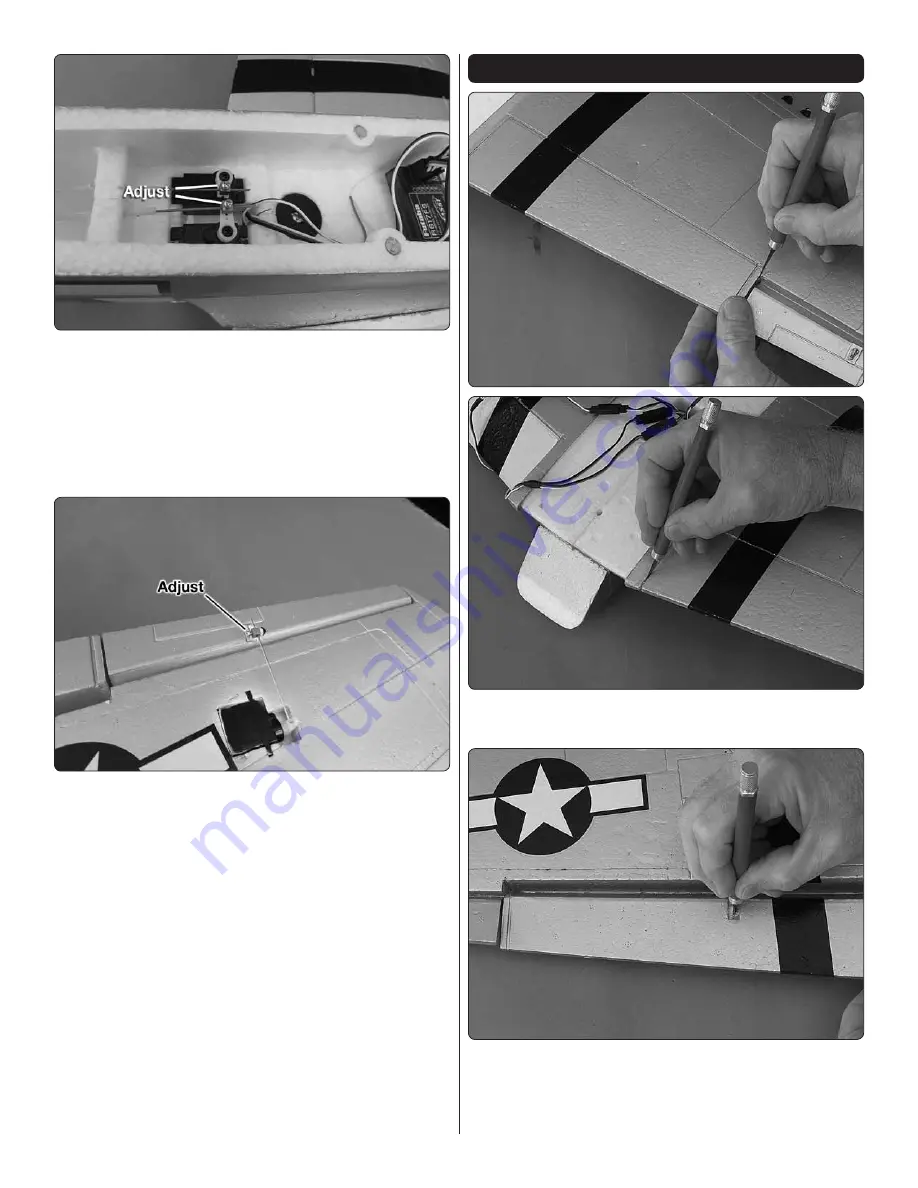
OPTIONAL FLAP INSTALLATION
❏
1. Using a sharp hobby knife cut the end of the fl aps loose
from the wing.
❏
2. Cut a slot in the center of the fl ap control horn recess on
the bottom of the wing. Do not cut through the top of the fl ap.


