


– 26 –
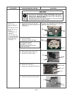
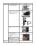
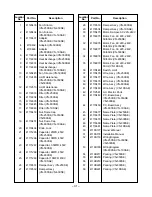
Position/Part
Replace/Assembly procedure
Description
Lock
knob
Lid
maintenance
Screw
Filter
Heat
Exchanger
Partition
board
Screw
Rail
Connector
Fan unit
Screw
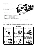
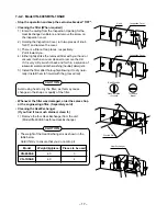
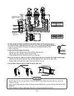
The figure is for VN-250SE. The configuration
differs according to the model.
1) Remove the screw, turn the lock
knob by 90°, and then remove the lid
maintenance.
• Filter 1), 2)
• Heat exchanger 1),
3)
• Fan sirocco 1) to 8)
• Motor fan 1) to 9)
• Damper
1), 2), 3),10), 11)
• Capacitor
12), 13), 14), 15)
• P.C. board assembly
(including terminal
block and relay)
12) to 16)
2) Remove the filter.
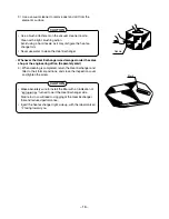
3) Remove the Heat Exchanger.
The weight of the heat
exchanger is 3 to 7kg.
Hold the Heat Exchanger hard
without dropping it.
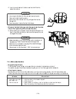
4) Remove the screw and the rail.
5) Remove the partition board.
Nut
Fan
sirocco
6) Remove the connector.
7) Remove the screw fixing the fan unit.
8) Remove the nut and the fan sirocco.
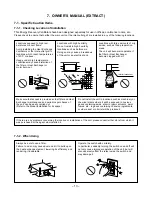
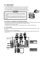
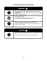
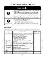
WARNING
• Be sure to turn off the power supply of distribution panel, power
board, and etc. before the work when power-ON is unnecessary
such as a case of disassembling.
Otherwise an electric shock may be caused even if the wall switch is
turned off because it is a single cut switch.
Turn off
the power
supply.
Summary of Contents for VN-1KSAE
Page 32: ......


