– 12 –
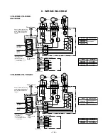
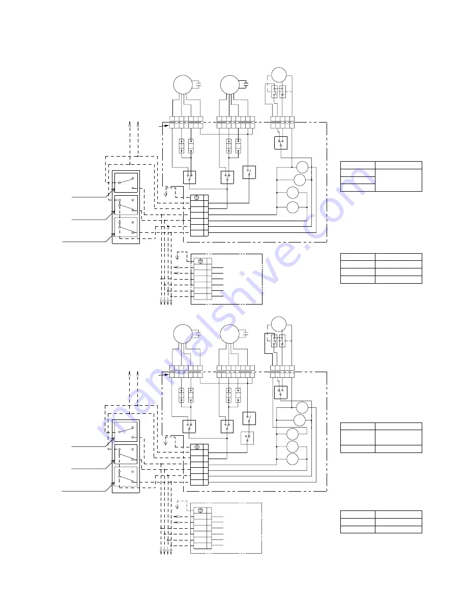
6. WIRING DIAGRAM
<VN-250SE, VN-350SE,
VN-500SE>
1 2 3 4 5 6 7
1 2 3 4 5 6 7 8
1
2
3
4
5
6
7
1 2 3 4 5
1 2 3
4
5
1
2
3
4
5
6
7 8
1 2 3 4 5 6 7
1 2 3 4 5 6 7 8
1
2
3
4
5
6
7
1 2 3 4 5
1 2 3
4
5
1
2
3
4
5
6
7 8
MS
CN–
SAFM
CN–
EAFM
CN–DM
NC
NO
CM
3
1
4
1
RY4
RY4
CN8
CN6
CN5
CN7
RY5
RY2
RY5
RY2
RY3
RY3
TM1
4
3
2
1
6
COMMON
L
N
LOW
HIGH
DAMPER
7
5
NO
NC
CM
NO
NC
CM
NO
CM
4
3
2
1
6
7
5
TM1
L
N
LOW
HIGH
DAMPER
(1)
(2)
(3)
(4)
(5)
(6)
Power Source
(LINE)
(NEUTRAL)
(Srcond main body)
(Srcond main body)
Supply
Air Fan
Exhaust
Air Fan
Red
Orange
Capacitor
Red
Orange
Capacitor
Damper
Motor
Black
Common
Black
Common
Yellow
Low
Yellow
Low
Blue
High
Blue
High
Whte
Extra
High
Whte
Extra
High
Blue
Blac
k
Yello
w
(Heat Exchange)
White
(Nor
mal)
Third main body
Third main body
Power Source
Power Source
VN-250SE
220-240V~50Hz/
220V~60Hz
VN-350SE
VN-500SE
VN-250SE
2.0µF 450VAC
VN-350SE
3.0µF 450VAC
VN-500SE
3.5µF 450VAC
3
1
4
1
NC
NO
CM
CN8
CN6
CN5
CN7
NO
NC
CM
NO
NC
CM
NO
CM
NO
NC
CM
TM1
4
3
2
1
6
7
5
COMMON
L
N
LOW
HIGH
DAMPER
4
3
2
1
6
7
5
TM1
COMMON
L
N
LOW
HIGH
DAMPER
(1)
(2)
(3)
(4)
(5)
(6)
(LINE)
(NEUTRAL)
Operation Switch
(1) 0 (OFF)
(2) 1 (ON)
Air Flow Switch
(3) High
(4) Low
Operation Switch
(1) 0 (OFF)
(2) 1 (ON)
Air Flow Switch
(3) High
(4) Low
Function Select Switch
(5) Heat Exchange
Ventilation
(6) Normal Ventilation
To find out the function
of each switch.
Divide the power lines running
to the switch and the main unit.
On the product. do not attach
more then one cable to each
terminal.
Divide the power lines running
to the switch and the main unit.
On the product. do not attach
more then one cable to each
terminal.
Switch
(To be procured
locally)
Function Select Switch
(5) Heat Exchange
Ventilation
(6) Normal Ventilation
To find out the function
of each switch.
Model Power
Source
Model
Capacitor
VN-800SE
220-240V~50Hz/
220V~60Hz
220-240V~50Hz/
VN-1KSAE
Model
Power Source
VN-800SE
8.0µF 450VAC
VN-1KSAE
10.0µF 450VAC
Model
Capacitor
RY4
RY4
RY5
RY5
RY2
RY2
RY3
RY3
RY1
RY1
MS
Power Source
Supply
Air Fan
Exhaust
Air Fan
Red
Orange
Capacitor
Red
Orange
Capacitor
Damper
Motor
Black
Common
Black
Common
Yellow
Low
Yellow
Low
Blue
High
Blue
High
Whte
Extra
High
Whte
Extra
High
Blue
Blac
k
Yello
w
(Heat Exchange)
White
(Nor
mal)
CN–
SAFM
CN–
EAFM
CN–DM
Switch
(To be procured
locally)
<VN-800SE, VN-1KSAE>
Summary of Contents for VN-1KSAE
Page 32: ......

