DK40i Configuration
Expansion KSU
2-6
Strata DK I&M 6/00
Expansion KSU
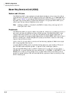
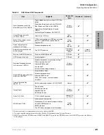
The optional DK40i Expansion KSU has four universal slots which can support Stratagy DK, loop
and ground start lines, DID and Tie lines, ISDN BRI lines and stations, Toshiba and analog
stations, and option interface PCBs. See
for detailed information on Expansion Unit
PCBs.
Table 2-5
DK40i Expansion KSU Components
PCB
Circuits per PCB
Interfaces
Connector
KCDU
2 CO line circuits/
4 digital telephone circuits
Central office loop start lines
RJ14C modular (CO Line
circuits)
Digital circuits same as PDKU2, except no DDSS
25-pair Amphenol (digital
telephone circuits)
PDKU2
8 digital telephone circuits
Digital telephones (with or without RPCI-DI or
ADM)
DDSS console
PDIU-DSs
DDCB
Cordless Digital Telephone (DKT2004-CT,
DKT2104-CT)
25-pair Amphenol
PEKU
8 electronic telephone
circuits
Electronic telephones
HDSS console
Alternate BGM source
EOCU PCB for OCA
External conference amplifier
HDCB
25-pair Amphenol
PESU
2 standard telephone
circuits/
4 electronic telephone
circuits (standard/electronic
telephone ports)
Standard: same as RSTU (no MW)
Electronic: same as PEKU, except PESU does
not support HDSS console
25-pair Amphenol
PIOU,
PIOUS,
RSSU
A PIOU or PIOUS can use an IMDU. See
for details.
25-pair Amphenol (PIOU,
PEPU)
Spring clip terminal (PIOUS)
IMDU
Remote maintenance 300 bps or 1200 bps full-
duplex modem for DKi Admin or DKi Backup. 1
per PIOU and PIOUS.
None
RBSU
2 ISDN BRI S/T circuits
(station or line)
1
ISDN BRI S/T TE-1s and Terminal Adaptors and
ISDN BRI S/T line circuits connected to an NT-1
adaptor.
RJ45
RBSS
Two ISDN BRI S/T circuits
(station only)
1 RBSS subassembly per RBSU. ISDN BRI S/T
TE-1s and Terminal Adaptors.
RJ45
RPTU
1 circuit/ISDN PRI
(8 or 12 B channels/1 D
channel)
POTS, FX, Tie (senderized & cut through),
OUTWATS (intra- & inter-LATA) and InWATS
RJ48C or RJ48X
ISDN TIA-568A
RDTU2
T1 lines (8 or 12 B channels/
1 D channel)
Loop start, ground start, Tie (wink or immediate)
and DID/DOD lines (wink or immediate)
RJ48M
2-pair amphenol (All PCB
amphenol connectors are
female)
RBUU
Two ISDN BRI U circuits
ISDN BRI U station- or line-side circuits
1
RJ11 or RJ45
RBUS
Two ISDN BRI U circuits
1 RBUS subassembly per RBUU. ISDN BRI U
station- or line-side circuits
RJ11 or RJ45
RWIU
8 or 16 digital circuits for
Strata AirLink
Up to four base stations (16 handsets max.)
RJ12 (6-wire modular jack)
Summary of Contents for Strata AirLink DK40i
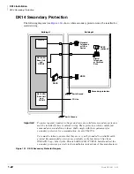
Page 22: ...Introduction Related Documents Media xx Strata DK I M 6 00 ...
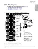
Page 48: ...DK14 Installation DK14 Wiring Diagrams 1 26 Strata DK I M 6 00 ...
Page 220: ...DK424 Installation Remote Cabinet Installation Instructions 5 68 Strata DK I M 6 00 ...
Page 262: ...DK424i Configuration Primary Reserve Power Cabinet Hardware 6 42 Strata DK I M 6 00 ...
Page 450: ...Universal Slot PCB Wiring Option Interface PCB Wiring Diagrams 10 42 Strata DK I M 6 00 ...
Page 592: ...Peripheral Installation Enhanced 911 Service E911 12 84 Strata DK I M 6 00 ...
Page 616: ...ACD Installation Spectrum Electronic Wall Boards 13 24 Strata DK I M 6 00 ...
Page 634: ...Fault Finding Fault Isolation Flowcharts 14 18 Strata DK I M 6 00 ...
Page 704: ...ISDN Interfaces ISDN Disconnect Cause Code 16 54 Strata DK I M 6 00 ...

